Today I leave you a protection circuit against overload and short circuit, which is homegrown, and can be used to protect power supplies or similar against overvoltage. It’s my first circuit, so there will surely be better ones, but you have to start with something: P
This circuit can be used together with other protections, such as a fuse to add more protection, protection against reverse polarity …
This circuit is pretty basic, and in it I combine a Shunt resistor to measure current, along with an op amp that amplifies the voltage to an acceptable value, and another that works as a Schmitt Trigger. If you don’t know what a Schmitt Trigger is, I recommend you go through my other post about what it is and what it is for. With the help of this Schmitt Trigger we achieve that this protection circuit against overload and short circuit remains in protection mode until the load is disconnected or the resistance increases a lot.
How it works

The circuit consists of three stages and a shunt resistor that has to be of a low value to affect the circuit the least. This shunt resistor can be of the order of 100mΩ, which will cause a 100mV drop in it for each ampere that circulates and will allow us to calculate the current.
Since the voltage in the shunt resistor is quite low, the first thing we will do is amplify this voltage so that it is useful to us. The first operational amplifier is responsible for this, which is configured as a non-inverting amplifier and with a gain of 20. With this gain, we will get an output of 2v for each ampere that circulates (0.1v * 20 = 2v).
Once the voltage is amplified, we will go to the second stage, which consists of an operational amplifier in Schmitt Trigger configuration. This circuit makes the protection only trip when its non-inverting input reaches a certain voltage, allowing us to decide with what current the protection against overloads and short circuits will trip. In the example above the Trigger fires at a voltage of 4v, and turns off when the voltage drops below 1v. Taking into account that the previous stage generates 2v for each A that circulates through the circuit, it means that the protection will trip when more than 2A circulate.
The third and last stage consists of a BJT transistor used to control the relay. This relay will activate the protection when the maximum current is exceeded. If you look at the circuit, the connection of the op amp that will measure the voltage is not next to the Shunt. This is to maintain the protection circuit even if the relay is deactivated and while there is a load. Otherwise the relay would start to oscillate, causing the voltage to turn on and off continuously.
Step by Step
Here I will explain step by step how the circuit works, although above I have already explained most of it.
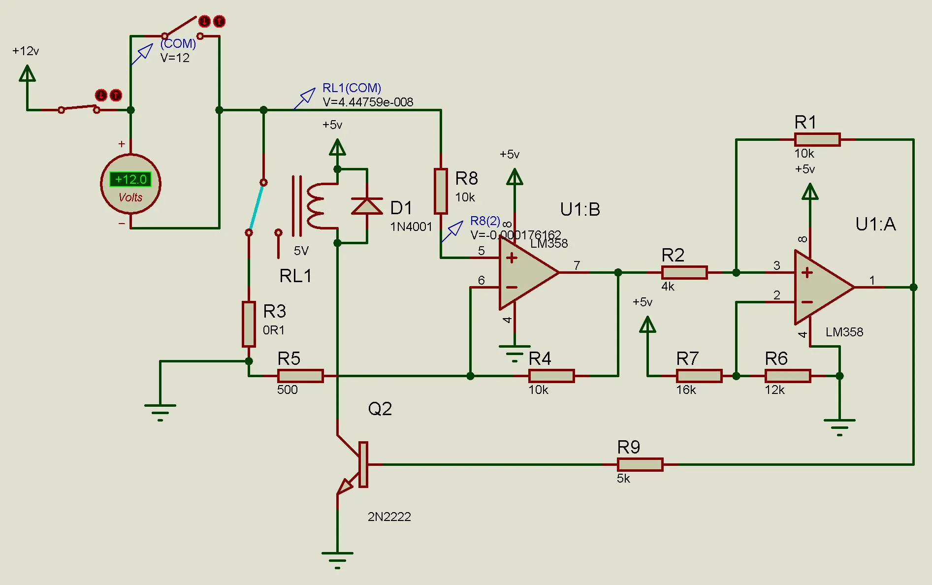
- With the circuit at rest and without load, the relay is at rest and keeps the circuit closed.
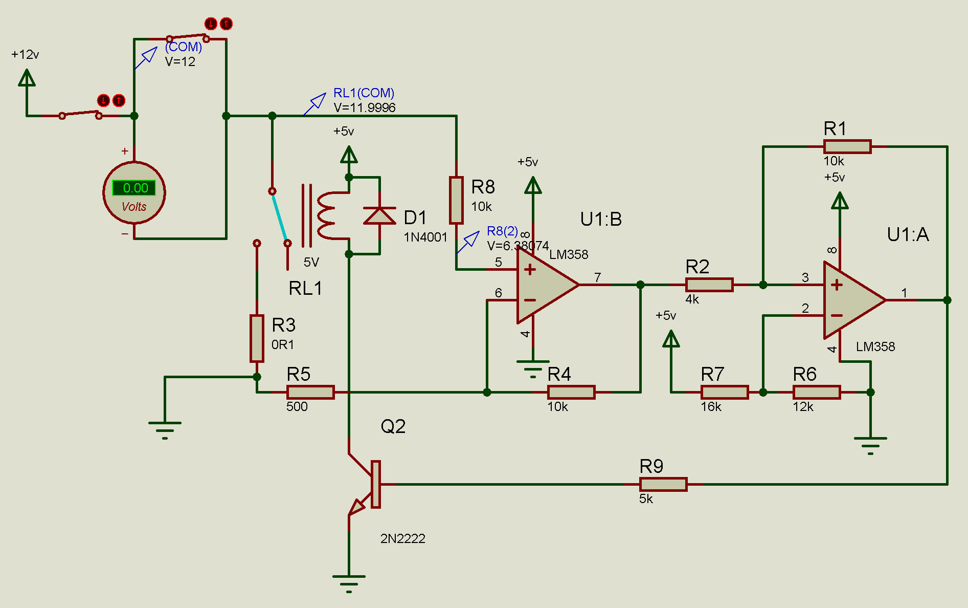
- When the load is connected (in the picture a voltmeter), the current flows normally. As the current through the circuit increases, the voltage between the pins of the shunt resistor (R3) increases. Upon exceeding the pre-set limit of 2A, the voltage is so high that it trips the Schmitt Trigger, activating the transistor and relay.
- Once the circuit enters protection mode, the relay opens and causes the voltage at the non-inverting input of the op amp to be practically that of the source. To get it to drop below 0.05v and for the protection to be deactivated, the load would have to be deactivated. Once done, the circuit will work normally again.

What if I want more current?, or less?
To modify the maximum current at which the protection circuit against overloads and short circuits trips, we can do it in several ways:
- Modify the shunt resistor, which modifies the voltage between its pins. With a resistance of 50mΩ we will get half the voltage to drop, and therefore it will trip at 4A. With a 200mΩ we will achieve the opposite, and it will trip with 1A.
- Modify the gain of the first op amp. This can be done simply by modifying R4, which can be changed to a variable resistor to make the protection adjustable.
For more information about how to calculate the profit, I recommend that you go through the following link. This may be the easiest and most comfortable way to do it. - We can also modify the trigger voltage of the Schmitt Trigger, making it trigger at 3v instead of firing at 4v. With this the maximum current will drop from 2A to 1.5A. This option is almost the least recommended, since it also modifies the voltage at which the protection is deactivated. By moving the voltage down one volt (3v), the lower firing range increases from 1v to 2v.
Well, so far the protection circuit against overloads and short circuits. As always, I hope you liked it, and if you have any questions or comments, do not hesitate to write below.
greetings!