In this tutorial I am going to show you what Schmitt Trigger is and what it is for.
A Schmitt Trigger is a type of logical input that will provide hysteresis or two threshold levels: high and low. This will allow us to reduce the errors produced by noisy signals, resulting in a square wave. In addition, it can also be used to convert other types of signals, such as triangular and sinusoidal, into square waves.

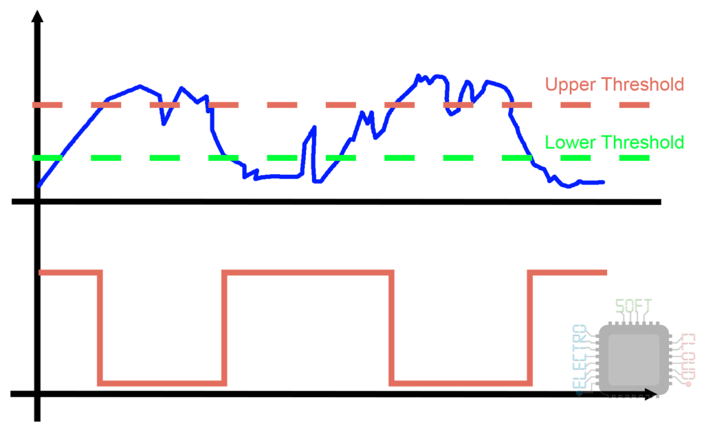
For example, if we have a very noisy input signal, it is possible that if our circuit has a single threshold it will not interpret the signal correctly.
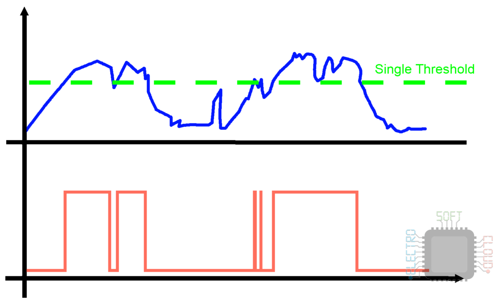
This in a digital circuit can lead to many problems due to erroneous pulses, so a Schmitt trigger can be used to correct it.
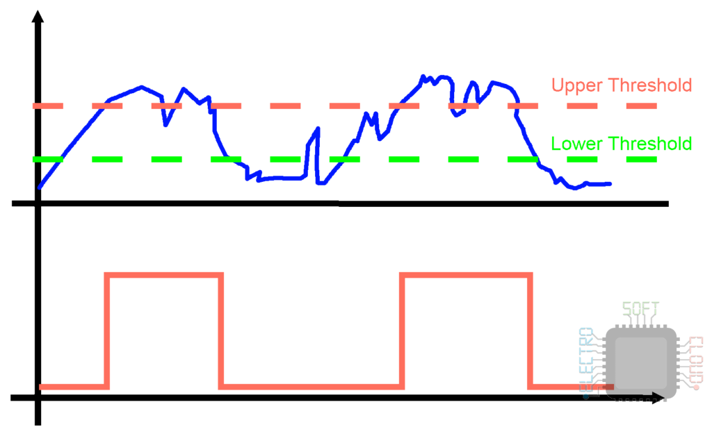
As it can be seen, having a double threshold has eliminated the erroneous pulses caused by noise, leaving a square wave.
Types of Schmitt Triggers
There are a lot of logic ICs with integrated Schmitt Triggers, but in case we need to create it ourselves, we can do it using op amps or transistors.
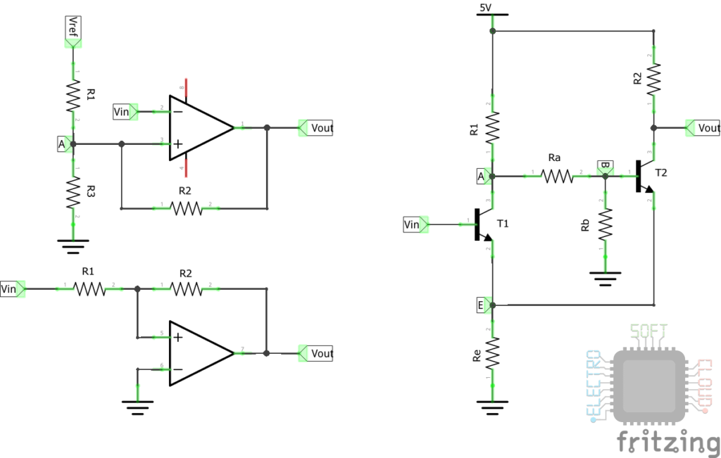
In this post we will focus on those based on Operational Amplifiers and on another occasion I will talk about those based on transistors.
Schmitt Trigger no inversor simétrico
The Operational Amplifier Schmitt Trigger is based on the comparator circuit:
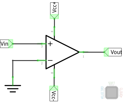
This circuit has the inverting input connected to ground or 0v, and the non-inverting input is connected to the signal input. As its name indicates, it compares the input signal, and if it is higher than 0v it connects Vcc+ to the output, and if it is lower it connects Vcc-.
If we add positive feedback to this circuit through a resistor and add another resistor between Vin and the inverter input, it will then become a Shmitt Trigger.
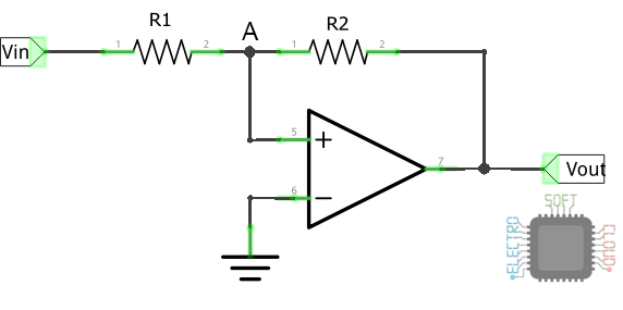
The operational circuit will continue to function as a comparator and will connect Vcc + when the non-inverting input exceeds the inverting input, and Vcc- when it is lower. The difference is that we have created a voltage divider at the non-inverting input that will allow us to extend the range of change.
How it works
Something that I did not see explained where I read about the Schmitt Triggers and that from my point of view is important, is the operation explained.
So far we have seen that the OP Amp works as a comparator, and that we must be above or below the reference voltage of the inverter input to switch between states. In addition to that we can see that the voltage of the inverting input is the product of a voltage divider between the output and the input.
That is why when the OP Amp has Vcc- connected to the output, to change the state we will have to increase the voltage of Vin until the non-inverting input exceeds the voltage of the inverter. Once this occurs, Vout will become Vcc + and therefore to change state we will have to lower the input voltage to achieve the opposite, that the non-inverting input falls below the voltage that the inverting input has. This is how the margin of change is achieved, which is the desired effect.
Formula explanation
You may wonder why I explain the formula before putting it on. It is more than anything because I want you to see how the formula is concluded.
For this we are going to assume that we have a symmetric voltage Vcc of ± 12v and that we want the Schmitt Trigger to change state to ± 6v. Taking into account that we have a voltage of 0v at the inverting input, these two voltage dividers come to mind.
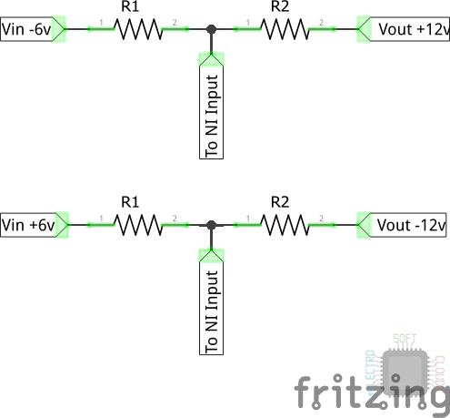
As you can see, both are symmetric, so the calculation can be done only once. To do this we will first have to change one of the resistances for a known value in order to calculate the other.
We are going to put a resistance R1 of 2K, and to calculate R2 we need to know the current that passes through it. This will be the same as the one that goes through R1, so the account is easy.

This reflection will lead us to the final formula.
Formula
The formula, as we explained in the previous section, assumes that the current that flows through R1 is the same as that that flows through R2:
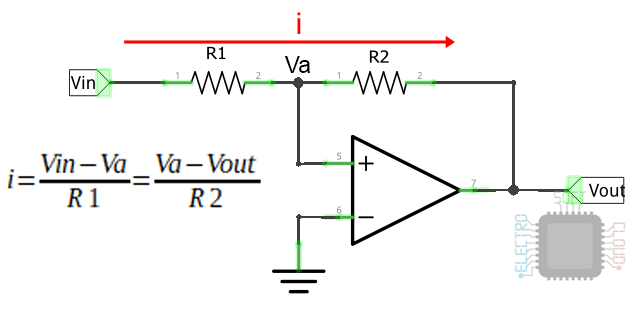
With this in mind, it is easy for us to get the value of R2. For this we clear the formula with the data we have, that we remember are:
- ±12v output voltage
- State change voltage ±6v
- R1 & 2K Resistors

As you can see, it is a simple rule of three that results in R2 having to be a 4K resistor. Of course this is in an ideal world, but considering that the Op Amp consumes, the switching voltage will not be exactly ± 6v.
Does it have to be a symmetrical font?
No, you can shift the reference voltage of the inverter input to also shift the range of voltages. The calculations I have not been able to find them at the time of writing this article, so I may put them in the future when I find them and check.
Schmitt trigger non-symmetric inverter
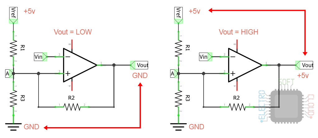
To achieve two non-symmetrical thresholds, we have an inverting Schmitt Trigger circuit powered by a single source. In this circuit Vin is connected to the inverting input, which will cause the output wave to be inverted, being 0v in the high peaks and 5v in the low peaks. Also, Vref is connected to the Vcc of the OP Amp directly.
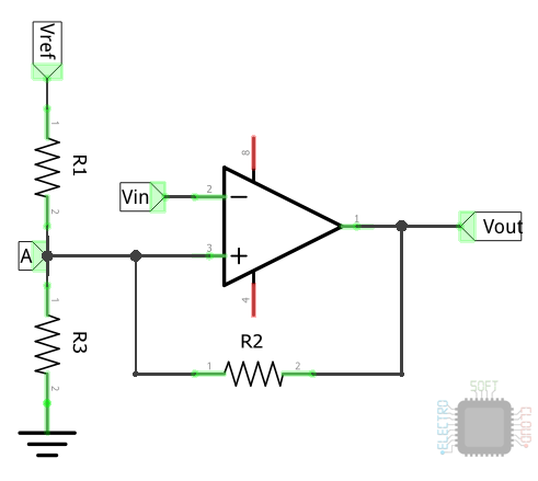
In this case the calculation is somewhat more complex and in order to calculate the thresholds we will have to calculate the result of the voltage dividers resulting from the combination of resistances:
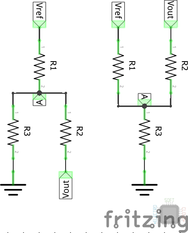
As you can see, to calculate the two states we have to calculate the voltage drop in two types of resistance configurations. These types of configurations are: parallel and voltage divider.
For those who do not understand where these two configurations come from, I leave you this image so that you better understand the two states.
Taking into account the above, it could be said that the calculation of A will be carried out with the following formulas:

Which are a combination of the equivalent resistance of the parallel resistors, along with that of a voltage divider. To simplify it, what we will do is separate the two calculations, first calculating the equivalent resistance of those that are in parallel. This will give us the following formulas:

Assuming that we use the voltage indicated in the formulas above 5v and 10k resistors for simplicity, the result would be as follows:

This gives us as a result that the above indicated circuit with a 5v input and 10k resistors each, would have a low threshold of 1.66v and a high threshold of 3.33v.
Notes
All calculations above are performed with the OP Amp being Rail to Rail. In the event that any other type of operational is used, it will be necessary to carry out the pertinent calculations, which I will possibly put in a future entry.
For more information you can take a look at the wikipeda entry about the Schmitt Trigger.
Greetings!

