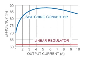
Today I’m going to talk a little bit about regulators, and the differences between linear regulators and switching regulators. Knowing the differences we can choose the regulator that best suits our project.
Transistor Zones
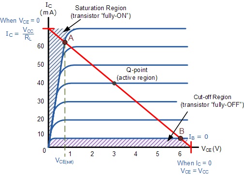
The first thing I am going to talk about is the transistor zones. Basically, because both regulators rely on transistors to do their job, either independently or integrated into an integrated circuit. That is why we must know the basic implications of each zone of the transistor, which are three.
Cut-off Zone
First is the cut-off zone, which is the zone where the default transistor is located. In this zone, the transistor will have the maximum resistance and will behave like an open switch, so it will not let current pass. By not passing current, there will be no heat loss.
Saturation Zone
On the opposite side to the cutting zone, we have the saturation zone. This zone causes the transistor to have the minimum resistance indicated in the RdsON data of the datasheet. In this state, the transistor will behave practically like a closed switch, letting all the current pass. In this case, having a very low resistance (especially mosfets), the heat dissipation will be minimal.
Active Zone
Finally there is the active zone, in which the transistor will behave as an adjustable resistance. In this area, the current flow of the transistor can be regulated, making it the one used by amplification circuits and regulators. In this area, the amount of heat dissipated by the transistor will depend on the voltage that falls on it, and on the current that passes through it (as in the case of resistors).
Linear Regulators
A linear regulator is a regulator that uses transistors to regulate the output voltage. These transistors work in the active zone, so they will act as resistors and therefore dissipate heat.
That is why its use is recommended for circuits whose input and output voltage are as close as possible, and in which the current is not very high, since they will generate a lot of heat and will require large heatsinks.
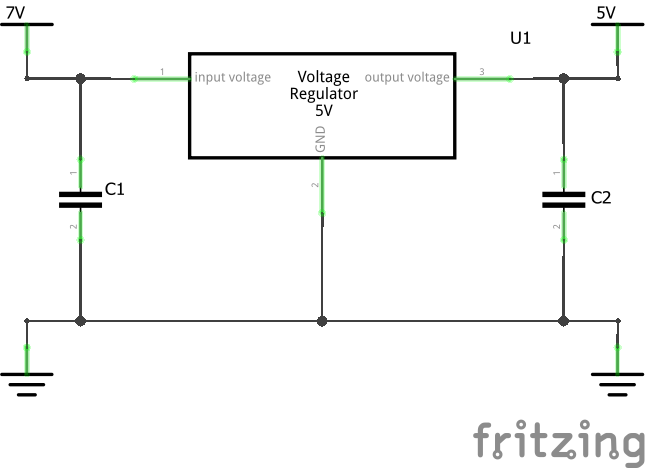
A typical linear regulator circuit would be as follows:
And the equivalent simplified circuit would be the following:
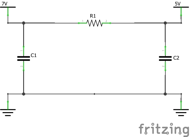
Obviously a regulator has more components involved in its operation than a simple resistance, such as a comparator, transistors, thermal protection …
The operation of these circuits is simple, since what they do is compare the output voltage with an internal reference voltage they have, and regulate the resistance of the step transistor to counteract the input voltage and keep it stable. This makes the output voltage very stable and with a very low ripple (depending also on the quality of the regulator).
The negative point of these regulators is their low efficiency, since the voltage drop that occurs in them is dissipated in the form of heat. That is why the more you gave the input voltage to the output voltage, the worse its efficiency and the greater its dissipation. So if, for example, we use an L7805CV regulator to get a 5v output from a 9v battery, we will be achieving an efficiency of 55%, and if we use a 12v battery, the efficiency will drop to 41%.
- Advantage
- Cheap
- Output with low riple
- No noise, making it better for sensitive circuits
- By not generating noise it does not interfere with sensitive circuits
- Disadvantages
- Low efficiency
- High heat dissipation, a heatsink may be necessary in some cases (which increases the cost and space required).
Switching regulators
Switching regulators, unlike linear regulators, work in the transistor’s cut-off and saturation zones, so the heat dissipation will be minimal.
That is why they are optimal for use with high currents or large voltage differences between input and output. It is possible to have a switching regulator with a 20v input and a 5v output and not need a heatsink for it.
In contrast, these circuits are more complex to design and more expensive, since they need a switching controller, a power transistor and a minimum of input and output filters.
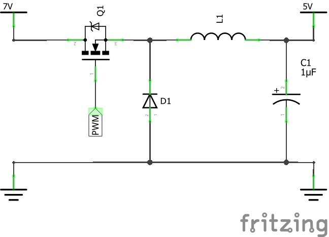
A basic regulator switching circuit would be the following:
And its simplified equivalent:
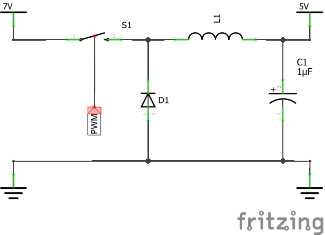
The operation of this circuit is somewhat more complex than that of the linear regulator, and is based on “switching” the transistor with the PWM signal. This signal will control the time the transistor remains in each state (cut-off and saturation), adjusting depending on the load demand.
If, for example, we connect a led diode to the output, this will demand little current, and therefore the pulse width of the PWM will be reduced to maintain the voltage. Also, if we connect a motor, the pulse width will increase to deliver the requested current without lowering the voltage.
The PWM signal is a square wave signal with two states (HIGH or LOW), which will control the state of the transistor and the time it is in each:
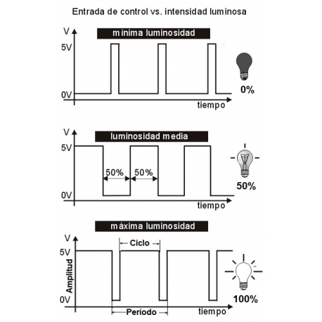
And thanks to the LC (Coil and Capacitor) output filter, the output voltage will be the resulting actual voltage or RMS.
- Advantage
- Much more efficient, being able to exceed 85% efficiency
- They hardly generate heat, so you will not need the heatsink that takes up so much
- Not generating much heat, they can withstand currents of several amps
- They do not dissipate more heat by increasing the voltage difference between the input and output
- The operating frequency is high, so the ripple can be very low.
- Disadvantages
- More complex to make and therefore more expensive
- They generate switching noise, so it is recommended to also add filters to your input to prevent it from seeping into other devices.
- If your circuit is very sensitive, it may be affected by noise
As always, I hope you liked it, and do not hesitate to write anything.
Greetings!!

