Hello, in this guide I will teach you how to change the clock speed of our Arduino, so we can do without components, reduce consumption, use it with less voltage, or even overclock our ATMega328p.
Originally Arduino works at 16Mhz, but it is possible to change it so that it works at frequencies between 1Mhz and 20Mhz.
Requirements
The requirements are the same as for the basic circuit, only that we will also need the frequency oscillator that we want to set if it is using an external oscillator.
| Protoboard |
| Jumpers or connecting cables |
| One ATMega328p Chip |
| A 16Mhz quartz crystal and another one of the frequency we want (if applicable) |
| Two 22pf ceramic capacitors for 16MHz |
| A push button |
| 1k resistor |
Basic circuit
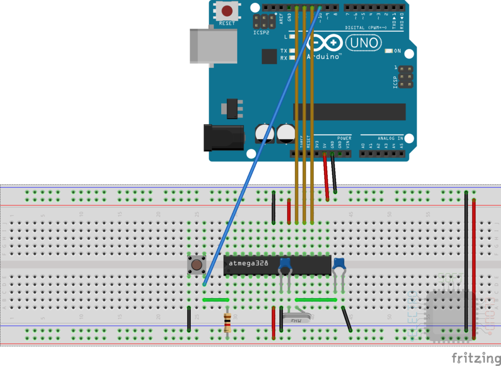
To be able to change the clock speed on our ATMega328 chip, we will have to burn the bootloader, so it is not possible to do it directly on the board and we will have to mount an external basic circuit.
Since I already explained how to do it in my other post some time ago, I will avoid going through the branches explaining again how to do it. So I will limit myself to putting the assembly scheme, but if you want to know more I recommend you stop by that post.
How does it work
Arduino, internally has an 8Mhz internal oscillator, so we can use it with lower frequencies without an external oscillator. On the other hand, it is capable of working with frequencies of up to 20Mhz with an external oscillator, which will give us a wide range of frequencies. This will be done by modifying the “fuses” of the bootloader and installing that bootloader, but since it is already done, we will only have to burn the bootloader.
Frequencies
I leave you a table of frequencies at which our ATMega328p can work at the time I made this entry, since that table can change (it did last month by adding several more frequencies). In this table I also indicate if it can be done using the internal oscillator, or if on the contrary we need an external one. Obviously the internal oscillator only works up to 8Mhz, so the frequencies above that will be out of reach.
| Frequency | Internal Clock | External Oscillator |
| 1 | X | X |
| 1.8432 | X | |
| 2 | X | X |
| 3.6864 | X | |
| 4 | X | X |
| 7.3728 | X | |
| 8 | X | X |
| 11.0592 | X | |
| 12 | X | |
| 14.7456 | X | |
| 16 | X | |
| 18.432 | X | |
| 20 | X |
To consider
In addition to those stated above, there are two very important things to keep in mind.
The ATMega328 has to work to be able to burn the bootloader, otherwise it will not respond to the burning commands. It is not worth mounting a circuit to run at 4Mhz and trying to burn the bootloader on a chip programmed at 16Mhz. Since the microcontroller will not start, we will not be able to burn the new bootloader.
Also, you will need to have the components on hand, and this is very important. If you burn the ATMega328p bootloader at 20Mhz for example, without having a 20Mhz oscillator, you will not be able to use it or burn another bootloader until you get this crystal.
Capacitors calculation
Another important thing to consider is the calculation of the capacitors. We cannot use a 22pf capacitor for all frequencies as it will not work properly. This is why we have to achieve a balance between the capacitance of the capacitors in “parallel” (added to that of the circuit), with the capacitance of the quartz crystal.
For this, the first thing we have to know is the CL (Load Capacitance), of the quartz crystal. To find this data, we will have to look it up in the datasheet of our quartz crystal, or see if the store can provide it to us.

In addition to this data, we will have to know the capacitance of our circuit, but since that is difficult, we will normally use a value between 2pf and 5pf (we will call this capacitance Cstray).
Knowing these data, we will have to use the following formula to calculate the capacitors:
CL = ((c1 * c2)/(c1 + c2))+Cstray
Since we know CL and Cstray, we will start to solve the equation by moving Cstray to the left of the equal, making it negative, of course.
CL – Cstray = (c1 * c2)/(c1 + c2)
Substituting the above for their real numbers, we would be like this:
20 – 2 = (c1 * c2)/(c1 + c2)
The previous formula forces us to perform the calculation several times with different capacitor values, so for simplicity, I personally use a spreadsheet.
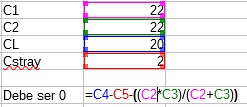
With this simple spreadsheet, we can easily find suitable capacitors. The closer the formula box is to zero, the more stable it will be.
Installing the necessary software
I will assume that you already have the Arduino IDE software, so I will go directly to the installation of the microcontroller management package. To do this, we will follow these steps.
The first thing will be to add the download URL of the cards in the Arduino IDE. For this we go to File > Preferences
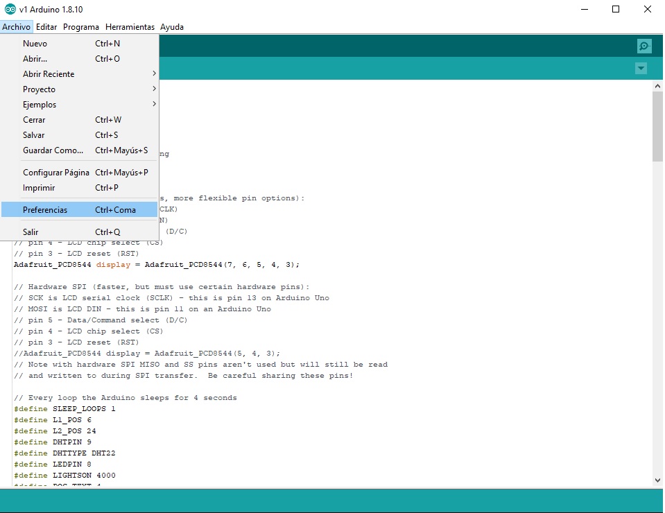
In the new window that will open we will give the button for the manager of additional URLs of cards
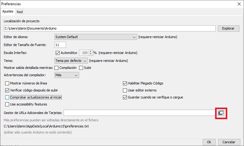
And in the new window that will open, we will add the following url:
https://mcudude.github.io/MiniCore/package_MCUdude_MiniCore_index.json
And finally we close the two open windows giving OK. Once the above is finished and the URL of the plates is added, we will proceed to install it. For this we will open the card manager by going to the menu Tools > Board > Card manager.
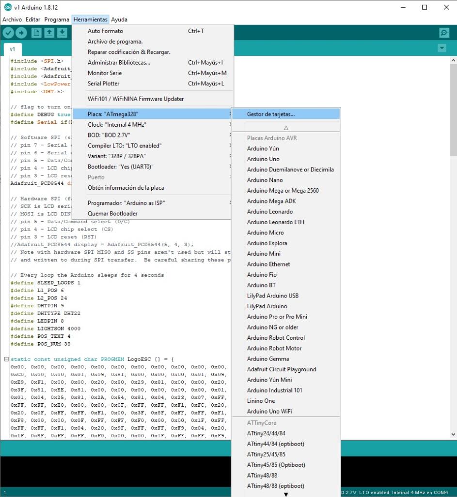
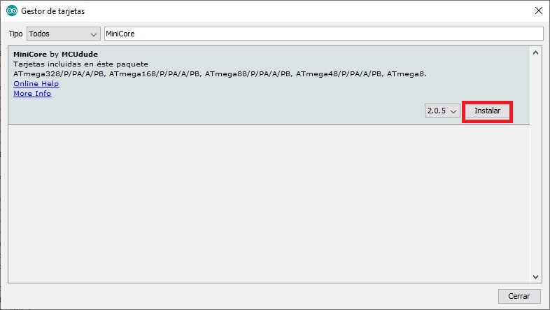
There we will look for the MiniCore package and we will install the latest version
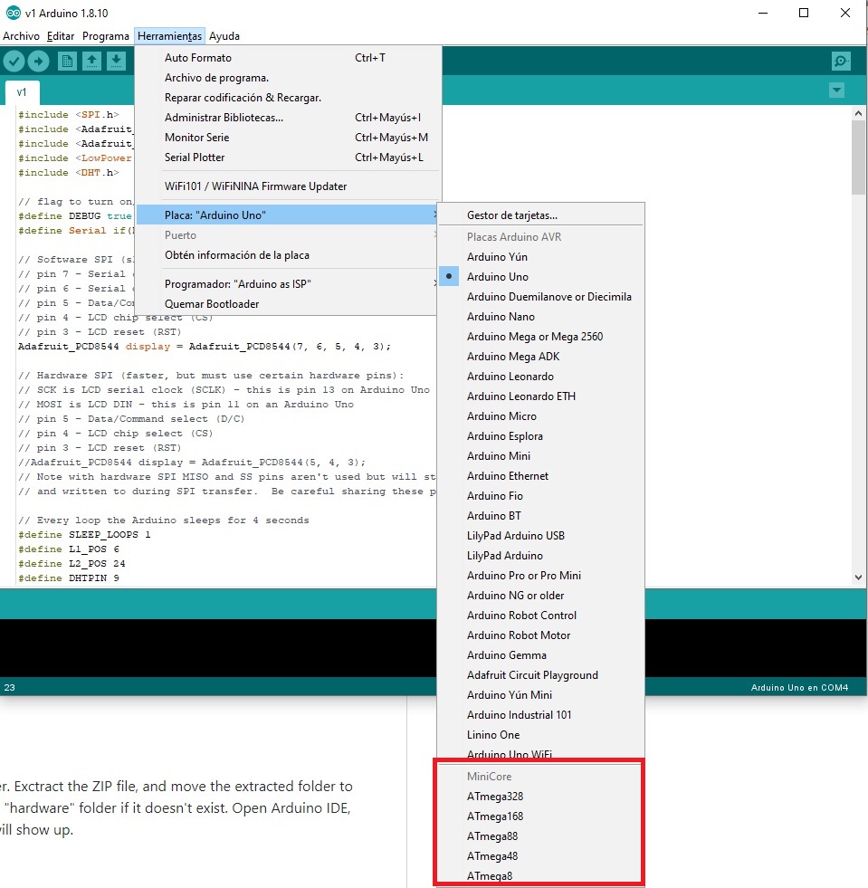
Once installed, we can see that we have several new boards to select from, among which is the ATMega328p.
Modifying the clock speed
Now that we have everything installed and ready, we need to burn the bootloader to be able to modify the clock speed of the ATMega328. For this, we will have to assemble the basic circuit that I put at the beginning of the post, and upload the ISP sketch to the Arduino that we will use to burn it. For more information I recommend you stop by the post that I indicated at the beginning, about how to burn bootloader and program a basic Arduino.
Once we have it, we will have to select the chip that we want to modify, which in our case will be ATMega328.
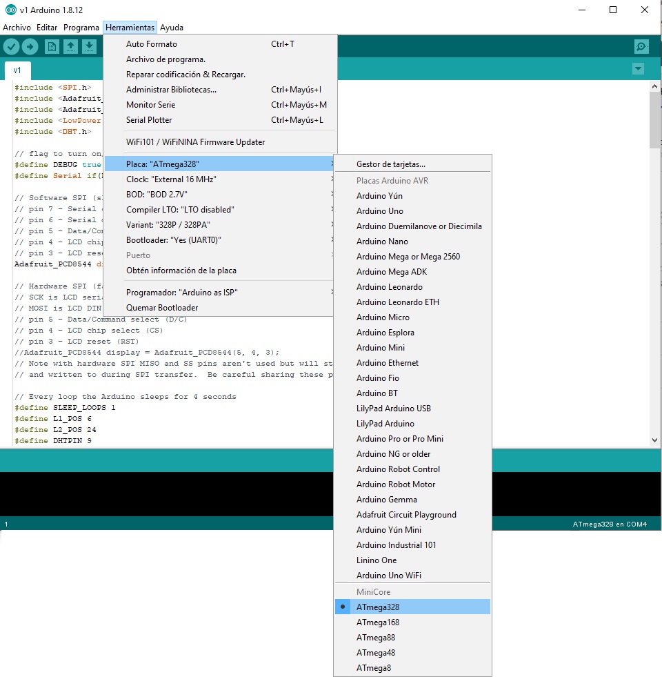
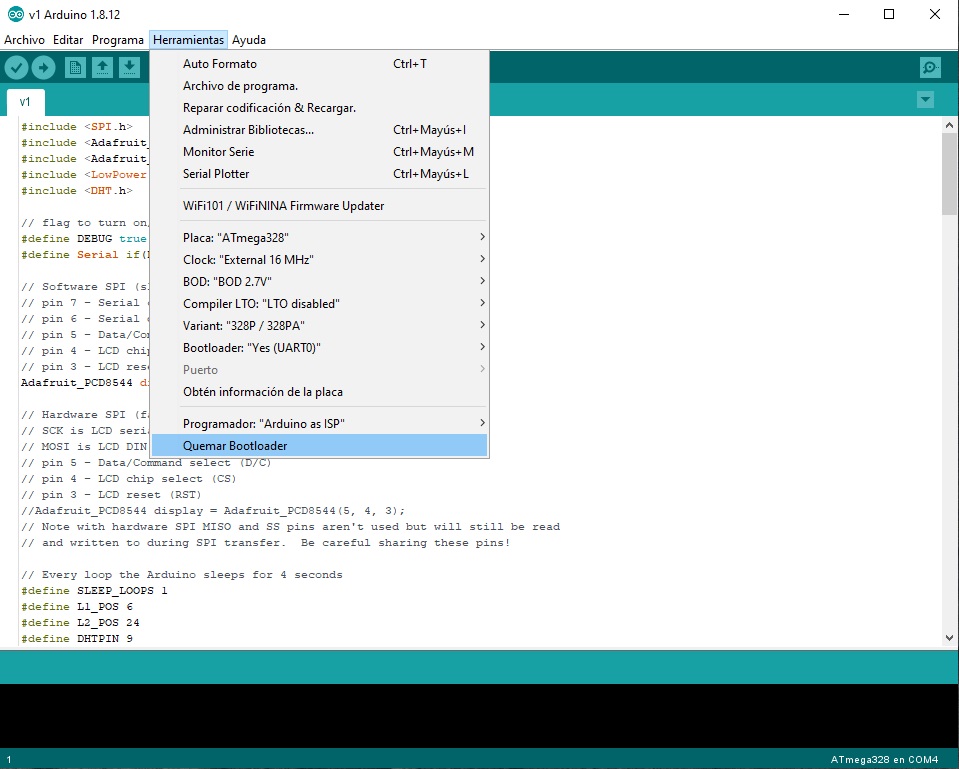
Once selected, several more options will have appeared in the tools menu for the choice of clock speed, BOD, Compiler LTO … which I will explain below.
Available options
- Clock: This is easy, it is the clock speed that we want our chip to have after burning the bootloader. We will consider selecting internal or external depending on whether we will use the internal oscillator, or on the contrary an external crystal.
- BOD: O Brown-Out-Detection, is an Arduino protection against brownouts. This protection disconnects the chip when it reaches a certain threshold to avoid damaging it. If you underclock your Arduino you can lower this voltage to allow it to run for longer for example.
- LTO Compiler: This option activates some compiler optimizations. These optimizations can help reduce the size of the program and even improve speed.
- Variant: The chip variant we are using. As a rule unless you have a special variant, it should not be necessary to change this option.
- Bootloader: Finally we will see the option to add or not add the Bootloader. This option is more aimed at when we program our chip, and will allow us to free up the space that the bootloader occupies in exchange for removing the possibility of programming the chip by UART.
Burning the bootloader
Once the previous options are adjusted, we will proceed to burn the bootloader. To do this, we simply have to press the burn bootloader button that we have below in that same menu.
Program with the new clock speed
Paraphrasing myself again, I will say that since I already have a previous post on the subject, it is best that you stop by to see it. That if a detail that we should not forget when programming our modified ATMega328, is that we have to do it by selecting the same clock speed. In case of not selecting it, our chip will work with the decompensated speed and it is probable that our program goes very slow, or on the contrary, very fast.
I hope this entry has served you, and remember that any constructive comment or suggestion is always welcome.


Thank you for this very educative article! Several months I tried to adapt an experimental ATmega board to the Arduino enviwonment with different clock speed, without success. I never got what to change to support the speed with a functioning serial interface. This did work at the first try!