
In this case I am going to bring you a guide about the basic circuit and programming of an ATTiny85.
The basic circuit is very simple and only needs a resistance as an external component, unless we want to vary the clock speed with an external crystal. To keep this guide simple for the time being I will not talk about how to do it, but possibly I will in the future.
Pinout
The first thing we need to know how to connect our ATTiny85 is to know its pins. For this I bring you this image, which includes the basic data about the pins.
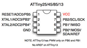
We also have a more advanced scheme, for the one above you are short of data 😛
Basic circuit
As I mentioned at the beginning, the basic circuit of an ATTiny85 microcontroller only requires a pull-up resistor to avoid resetting. This resistance is not necessary for it to work, but if we do not put it, we run the risk that our microcontroller will restart due to the electrical noise in the environment.
Optionally you can put a button to connect the reset pin to ground and proceed to reset the microcontroller. Obviously, said button is optional and it is not necessary to include it in our circuit.
With this in mind, we will only need the following components:
- ATTiny85: The evil brain behind the circuit
- One 4.7k resistor: Pull-Up to avoid resetting
- One push button (optional): Used to reset the microcontroller
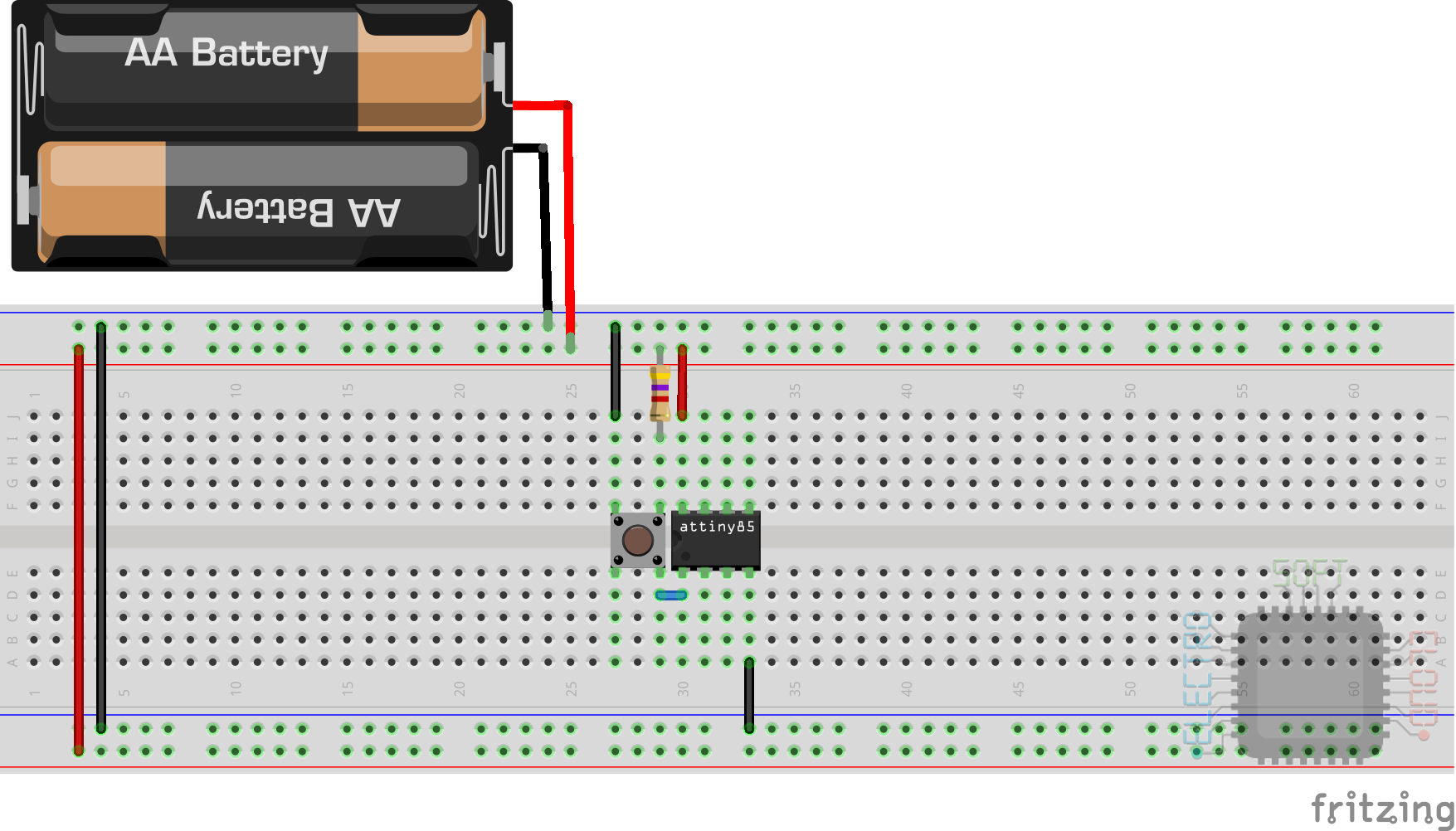
There we see that the circuit is quite simple, and this microcontroller can work with voltages between 2.5v and 5.5v. This will allow us to feed it with two or three batteries without problem, or with a standard 3.7v lithium battery.
Here is the datasheet in case you want to see more information about this microcontroller.
Having the ATMega328, why use it?
Like everything in this world, everything has its use. In the case of the ATTiny85 it can be for cases where we need a microcontroller that uses less and consumes equally little. If we compare it with the ATMega328p we find a microcontroller that takes up much less (speaking of the standard package of DIP8 vs DIP28). Furthermore, the consumption of ATTiny85 is half that of ATMega328.
As disadvantages we can find that it has much less IO ports, less memory of all types (SRAM, EEPROM and program).
It is true that in power they could be compared, since certain models of the ATTiny328 can reach 20Mhz with an external oscillator. Still, it is clearly at a disadvantage, but as I said at the beginning: everything has its place. It may be that we make a thermostat and it is not worth spending an ATMega328p and use the ATTiny85.
Program the ATTiny85
There is a bootloader for this microcontroller that will allow us to program it directly by connecting it to the USB, but bearing in mind that I intend this guide to be an introduction, I am going to teach you the standard method of programming. In any case, you would need this method to be able to install the bootloader that I indicate above, so I fixed that it is useful for you.
Prepare our Arduino
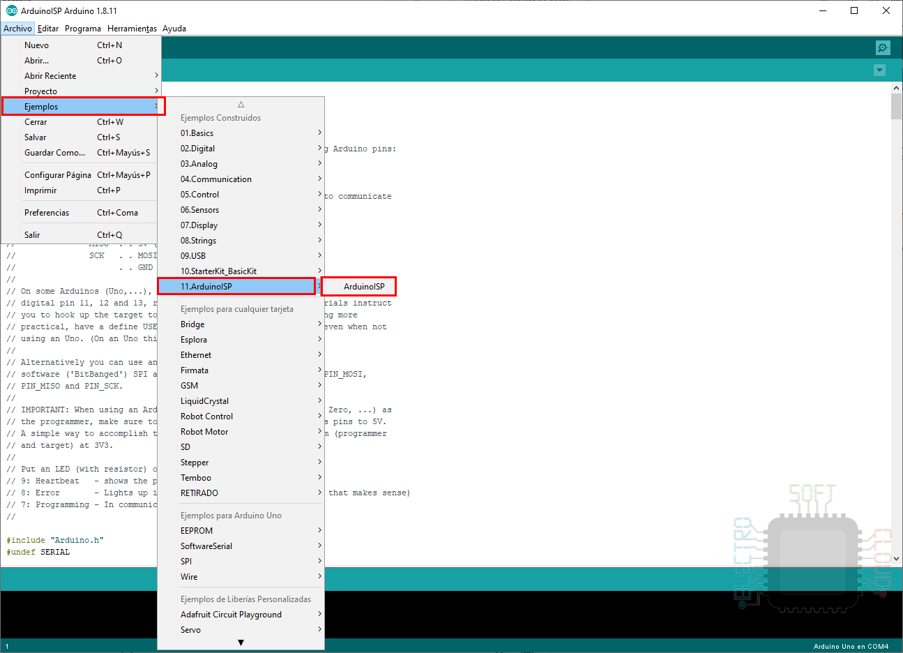
In order to program our ATTiny85 it is necessary that we have a functional Arduino that allows us to upload the sketch. Just like when we are going to program an standalone ATMega328p, it will be necessary to upload the AVR programmer example. To do this we will follow these steps:
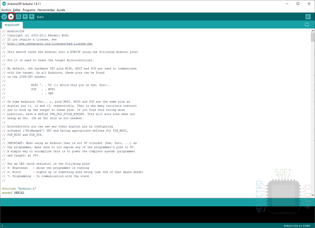
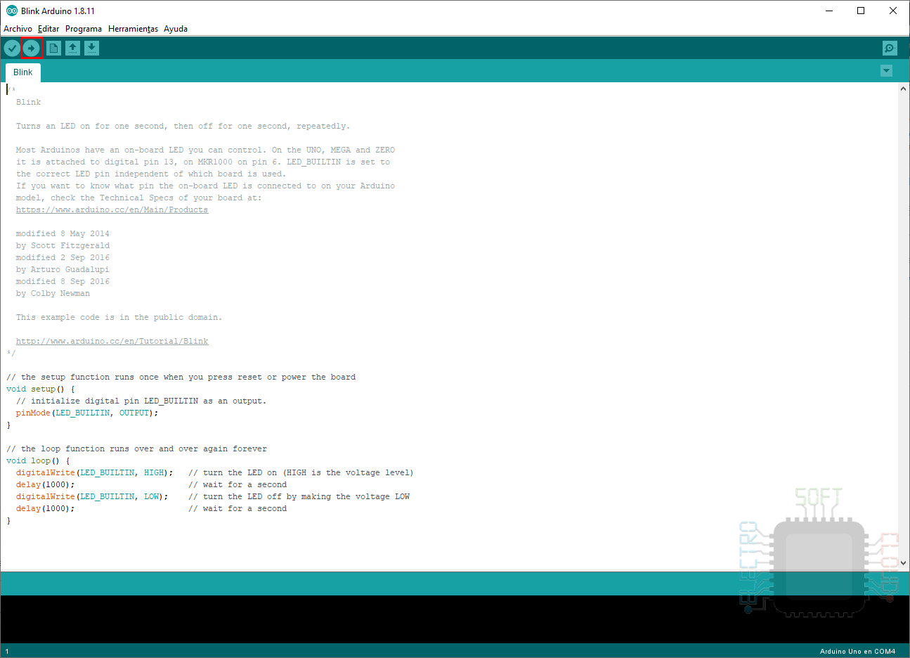
We open the developer’s sketch from the list of examples.
Once we have loaded the sketch, we make sure that the connection with our Arduino is well configured
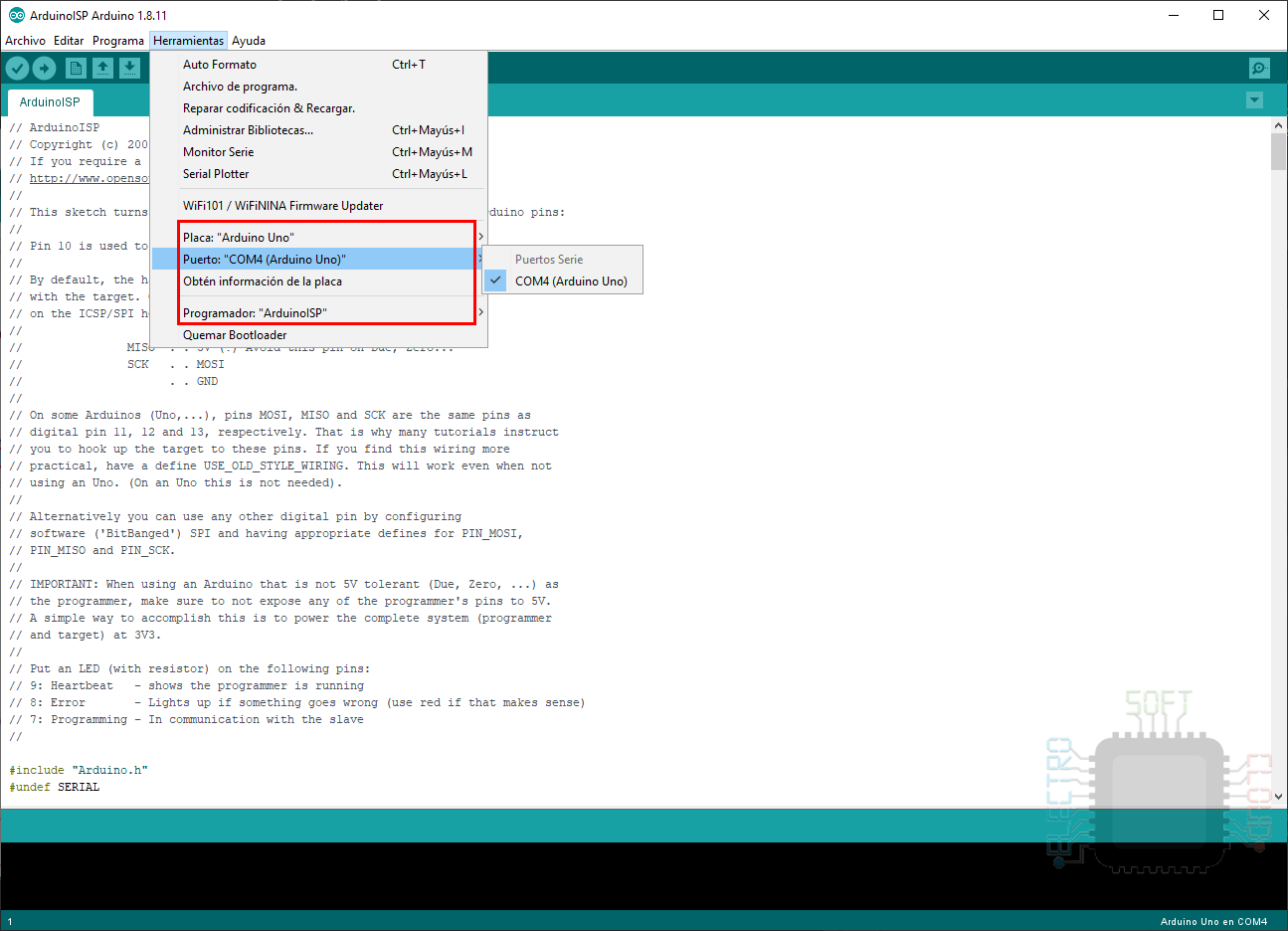
And finally we click on the button to program it with the example sketch.
Install ATTiny85 board configuration
Here we enter the “difficult” part of programming the microcontroller, since our IDE will not have the data to do so. To solve this problem, we will have to install the configuration data from a third-party website, for which we will follow these steps.
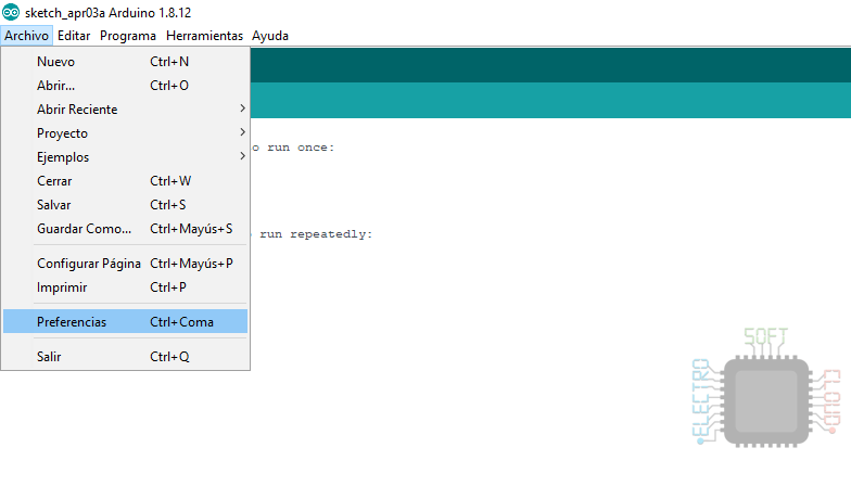
Vamos al menú File > Preferences
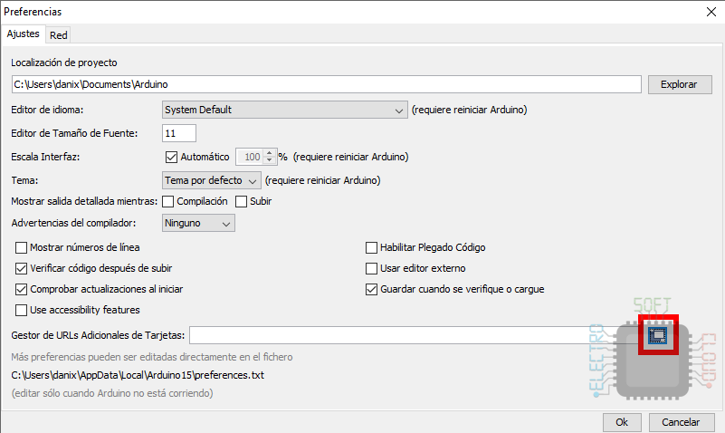
Click on the management button for the list of sources for cards
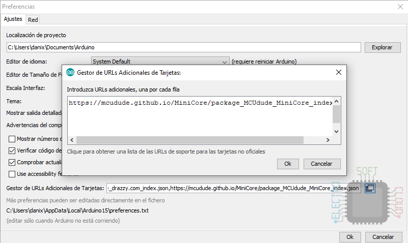
We add the following URL, making sure it is on a new line if we already have one:
https://mcudude.github.io/MiniCore/package_MCUdude_MiniCore_index.json
Once done we will accept all the screens that we have opened and go to the menu Tools > Board > Card manager.
In the new window that will open we will only have to search ATTiny85 and give the install button the only option that comes out.
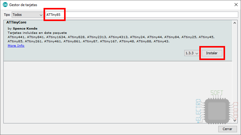
With this we will already have the board available in our Arduino IDE and we can program our ATTiny85 without problem.
Program ATTiny85
Well, we would have almost everything ready and now we only have the basic circuit and programming part, which consists of two steps:
- Assemble the basic circuit and connect the Arduino
- Upload our Sketch
The programming circuit is nothing more than the basic circuit that we have seen at the beginning of this post, with the only difference that we will connect our Arduino to use it as a programmer. For this, we will connect it as shown in the following image.
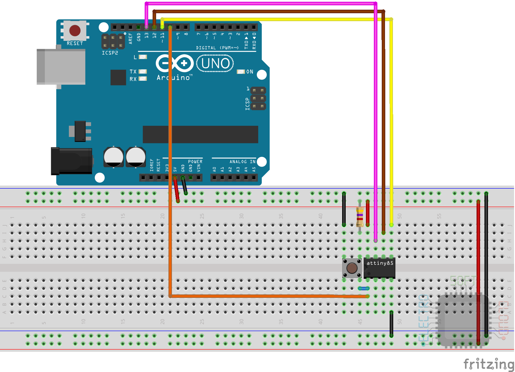
Once connected, we can proceed to upload our sketch. You will wonder why I do not show the step of burning the Bootloader as with the ATMega328p, and that is that as a rule our ATTiny85 is already prepared and is not necessary unless we want to change the clock speed.
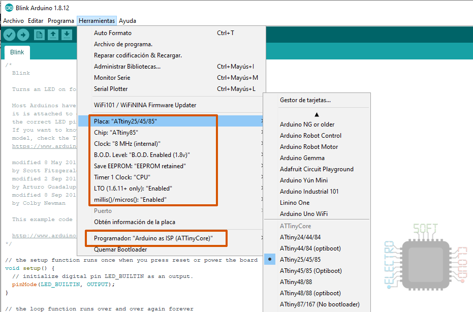
To upload the Sketch the first thing we will have to do is configure the chip in our IDE. Previously we already installed the card, so we should already have the options available in the Tools menu.
We will configure the options according to how we have prepared our ATTiny85, which for a factory chip would be the following.
Things like B.O.D and LTO will come disabled, but I recommend turning both on. The B.O.D will make sure to turn off our microcontroller when the voltage is too low, to avoid damaging it.
The LTO is optional, and what it does is that in some circumstances your code is smaller and runs faster. You can try turning it on and off and check for yourself if it optimizes your code.
Another important option to check is the programmer, since you have to use the Arduino as an ISP, but the one that comes with the ATTinyCore to make sure that it programs the chip correctly.
Once we have configured everything, we will simply give up, as we normally do.
So far the basic circuit guide and programming of our ATTiny85. I hope it serves you and greetings.
Hello,
I’ll consider it. Normally I use the spanish version, but there is no problem understanding the english one, so I can give a try.
Greetings!
Hi,
It would be nice if you used a standard environment (e.g. English).
That way, many more people would be able to understand the screenshots.
HTH.
Regards,
Willem