
In this tutorial I am going to teach you how to create a basic Arduino circuit, burn the Bootloader and do the programming directly on the breadboard. This is useful when we want to create circuits using independent ATMega328p, or we simply want to reduce consumption by eliminating extra components.
Among the advantages of this circuit are the price, since it consists of fewer components than an Arduino board. This helps if we have to create several equal circuits and we don’t need to be programming them. In addition, as I said above, by consisting of fewer components (including the regulator), it reduces consumption.
Of course not everything is good, and this circuit has certain disadvantages. Among them is the lack of the regulator, which is an advantage because it lowers consumption but will limit the input voltage. Another disadvantage is the lack of circuit to program it, so we will have to use an external one.
Index
- Pinout
- Basic Circuit
- Burning the Bootloader
- ATMega328p programming
- Using the Arduino board
- Using the schema used to burn the Bootloader
- Using the TX and RX connections
- Using a FTDI o CH340G pogrammer
Pinout
The first thing we should know about our ATMega328p is its pinout, in order to know how to connect it correctly.

Once we know how to connect the chip, we can proceed to create the basic circuit.
Basic circuit
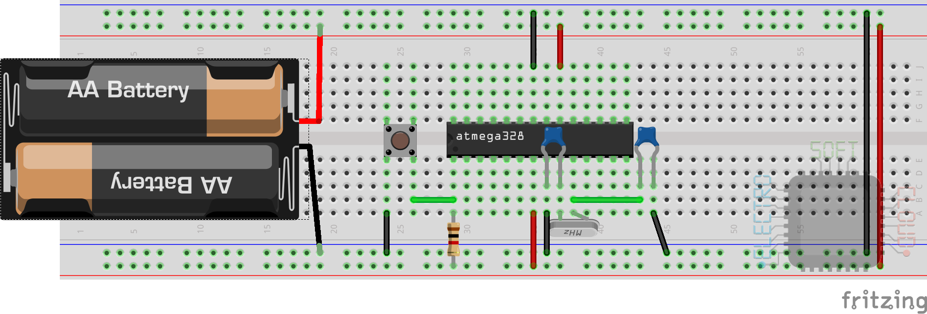
Once the introduction is done, we need to get down to work and start with the basic circuit. This circuit consists of the following components:
- ATMega328p. Of course, we need the beast’s brain
- 16 Mhz Quartz Crystal
- 2 ceramic capacitors of 22pf
- Push button for reset
- A 1k resistor to pull up the reset pin
With all the components in our possession, we can proceed to create our circuit on the protoboard following the following scheme:
To create this circuit I have based on the one included in the web of prometec , but I have removed the part of the regulator, which does not interest us for the purpose of saving energy.
Here is the datasheet in case you want to see more information about this microcontroller.
Burning the bootloader
Once we have our basic circuit mounted, we will have to burn the bootloader in order to start using our Arduino, otherwise we will not be able to program it. For this we need to have a functional Arduino, which will allow us to load the code for the bootloader burning.
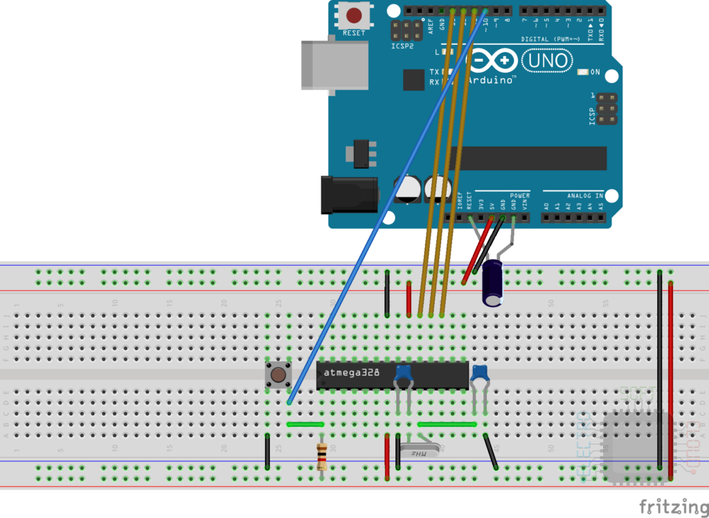
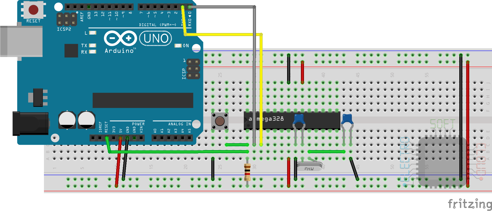
I have looked for ways to do it without another Arduino but I have not found any that is effective, or at least not as much as using an Arduino, so we will use the following scheme to do so:

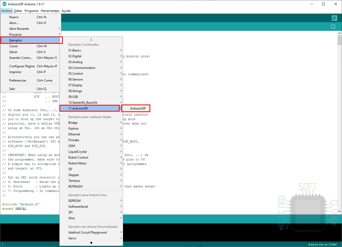
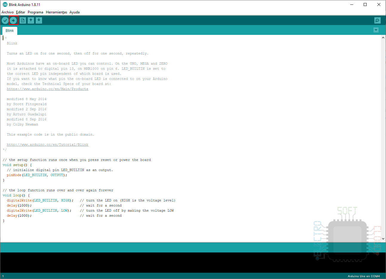
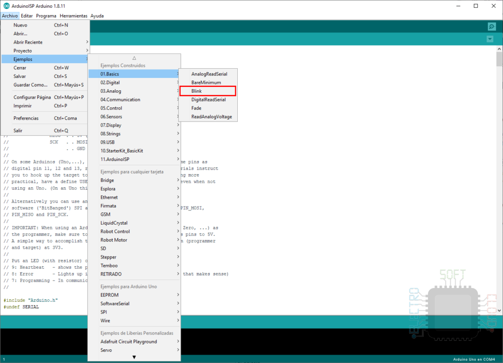
Once we have assembled the above scheme, we will have to connect the Arduino board via USB to the PC and load the ISP program. To do this we will open the Arduino application and load the sample code:
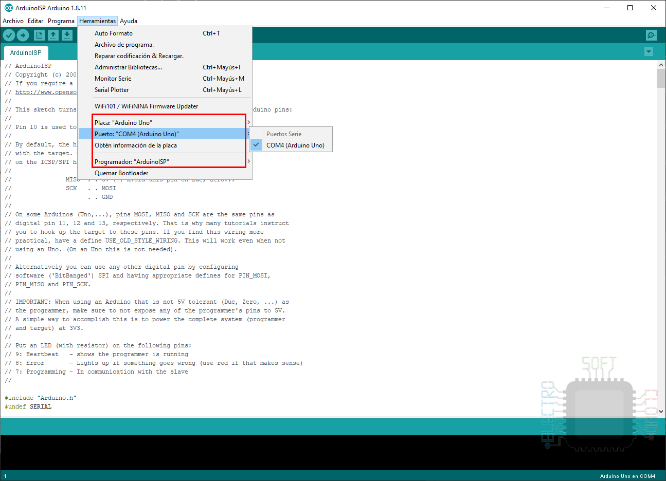
We make sure that the Arduino board is correctly configured in the program:
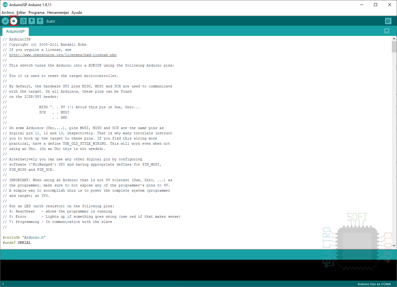
And finally we press the button to compile and upload the program to our Arduino:
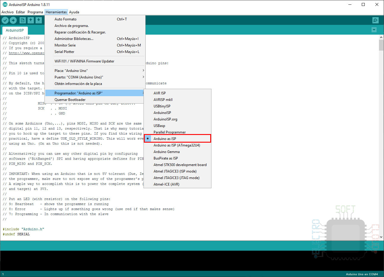
Once the program is uploaded correctly, we will have our Arduino ready to burn the bootloader. Now we just have to change the ArduinoISP programmer to Arduino as ISP:
And finally we will press the option of the same menu called Burn bootloader:
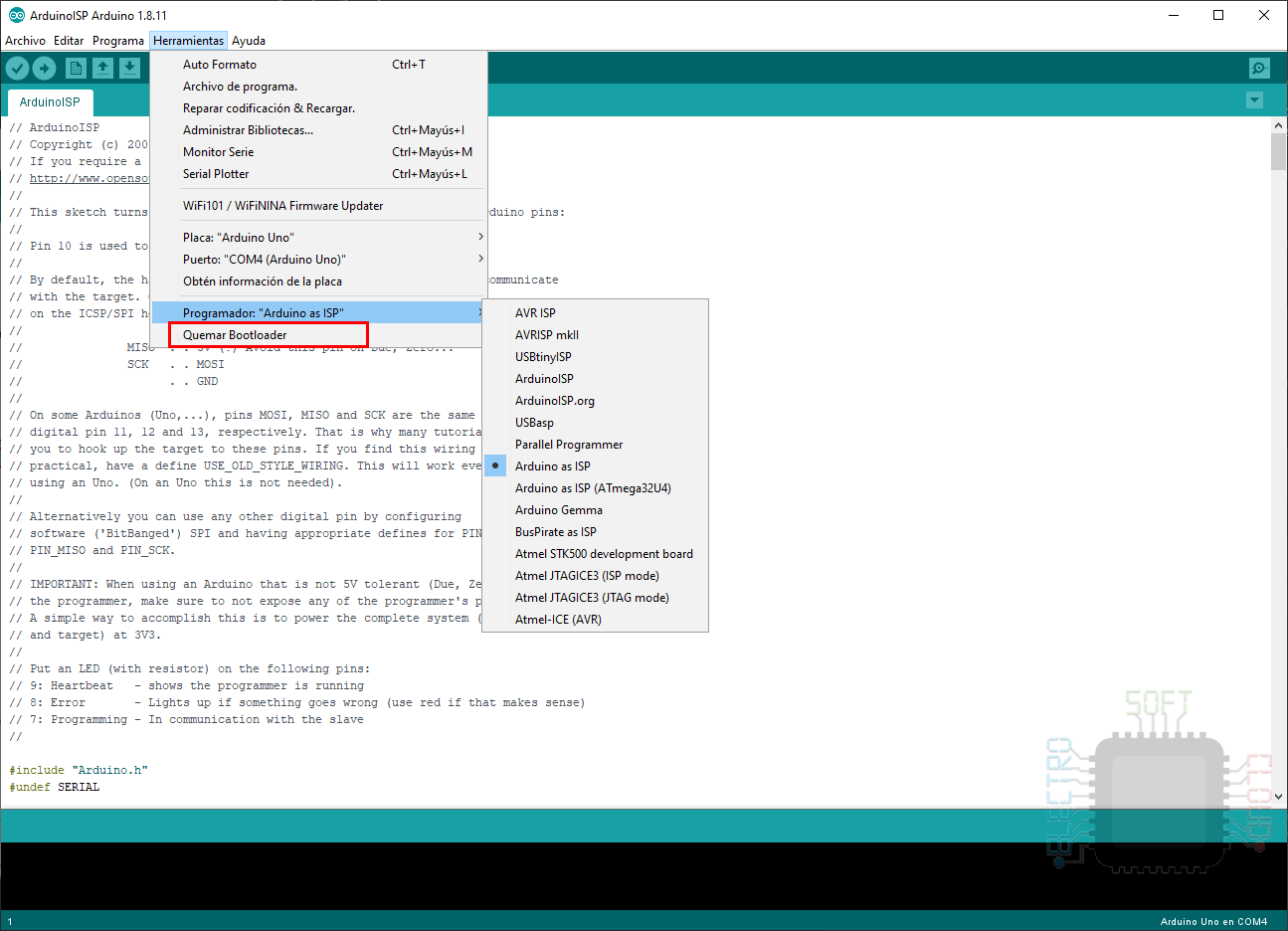
By pressing this button, we will see the bootloader burning process at the bottom of the program, and will tell us that the bootloader has been burned correctly.
If we receive any type of error, we will check the connection of the components to verify that everything is correctly connected, and if we continue to receive the same error, it may be necessary to put a 10uf capacitor between the Arduino reset pin and the GND pin. This is not necessary in the latest versions of the Arduino program, but just in case I leave the scheme:
ATMega328p Programming
Once the Bootloader is burned, we will only have to program the ATMega328p chip. This can be done by an Arduino, or a USB to UART programmer of the FTDI or CH340G type (the latter may require the installation of drivers).
Using the Arduino board
To program the ATMega328p from our Arduino we can use two methods:
- Using the method described above to connect it and use the Arduino as ISP
- Connecting it directly to the programmer of our Arduino board and program it normally
Using the schema used to burn the bootloader
If you burned the bootloader, perhaps the method described above comes to your hair because you already have the circuit mounted, so we will start with this method. To do this, we will connect the ATMega328p in the same way as when we burn the bootloader.

Once connected we will load our Sketch, which in my case will be the Blink example, and we will make sure that the programmer continues in Arduino as ISP.
Once done, we will only have to press the Sketch up button, keeping the shift key pressed.
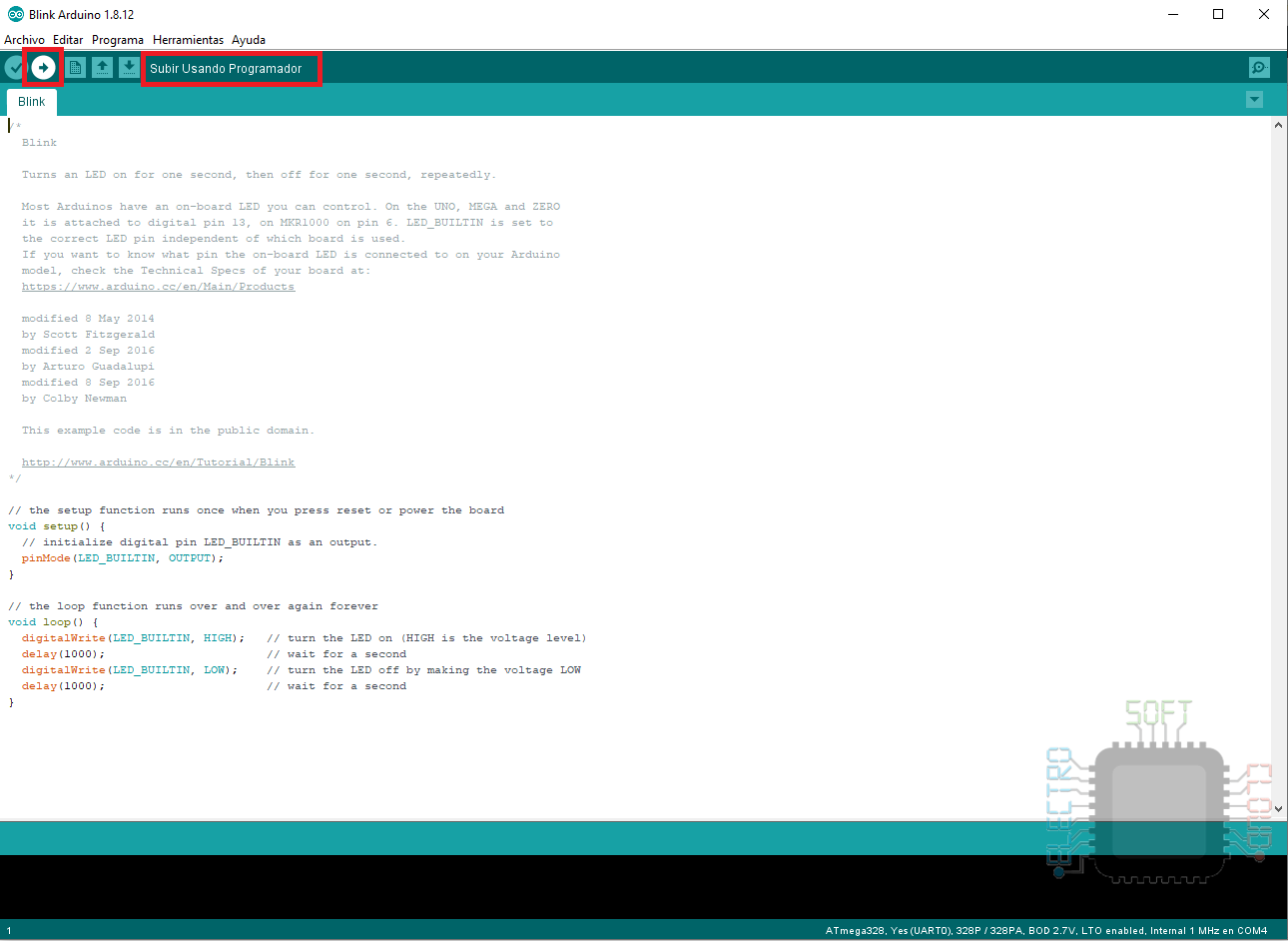
It is very important that we hold down the shift key while pressing the button, otherwise our Arduino will be the one programmed. If you look closely, you can see that the text changes to Upload Using Programmer
Using the TX and RX connections
This method is perhaps easier as well as more tedious. It is easier because we connect the Arduino board directly to the ATMega328p to program it, but more tedious because we will have to remove the chip from the board, otherwise it will not be possible to program it.
The connection scheme is basically to connect the Reset, RX and TX pins of our Arduino board to those of the ATMega328p.
Then we will configure the program as if we were going to program an Arduino Uno.
And finally we press the button to upload the Sketch (without pressing shift).
This will upload the code to our ATMega328p chip and make it ready to go.
Considering that we have had to remove the chip from our Arduino board, perhaps an easier way is to directly put the chip that we want to program on the board. Of course, we will have to be careful every time we remove it to avoid damaging the pins and of course, it does not work if we already have the chip soldered on a plate.
Using FTDI or CH340G programmer
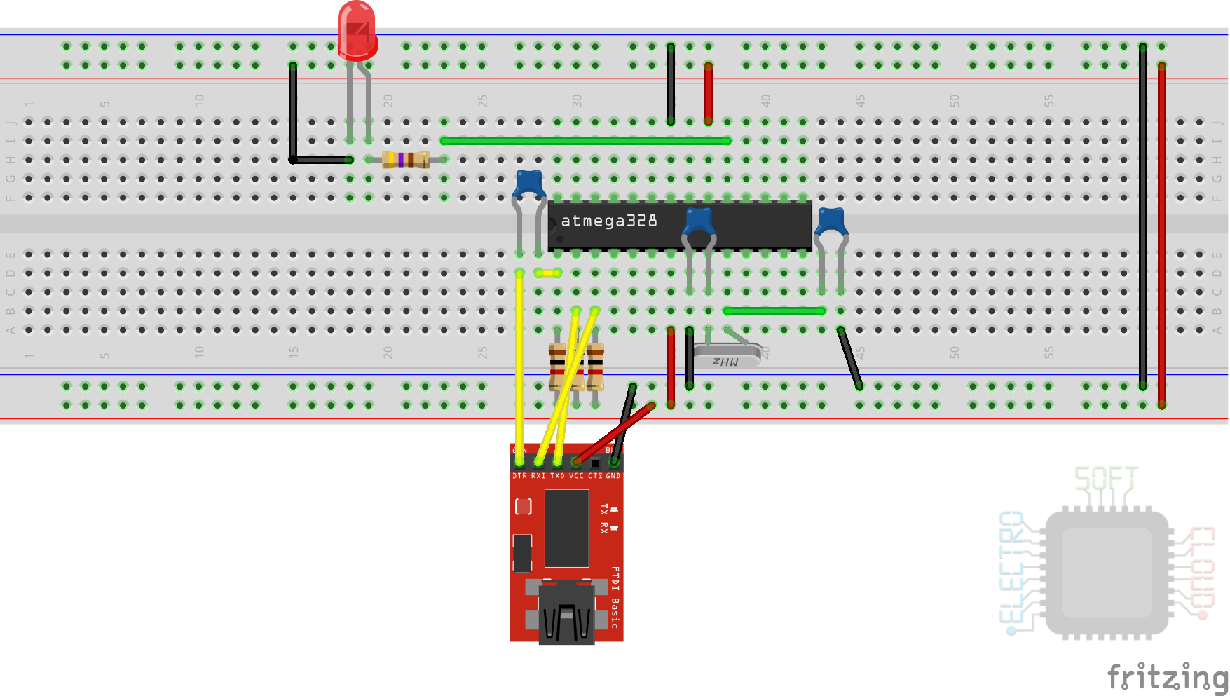
The other way to program our Arduino is using a serial programmer like the FTDI (for example FT232RL), or CH340G.
To do this, we will connect the programmer to our ATMega328p as follows (the LED is optional, but it helps us to verify it):
And once connected we will program the chip as if it were an Arduino. We make sure that it is well configured in the Tools menu:
Once done we load our sketch, such as the Led Blink, which we can use to verify the operation, as long as we had put the led:
And finally we will press the programming button:
Buen trabajo y muy bien explicado. ¡Muchisimas gracias!