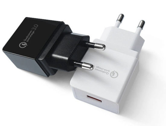
Hello, today I bring you something that I have been wanting to do for a long time. This is a variable power supply with Arduino and a QC3 compatible charger. With it we will get, for example, an output with a voltage range between 3.6v and 20v in steps of 200mv.
In summary, among the utilities of the power supply, we can highlight the power to adjust the output voltage. Also, we can use it to adjust the voltage required for our projects. If, for example, our project requires 12v to work, we can configure it at startup with this module, and thus make it compatible with QC3 chargers.
The first thing we have to do is install the QC3Control library, which will allow us to communicate with the charger easily and quickly. We can install this library through the IDE or by downloading it from its GitHub page, following the steps in my other tutorial.
Once installed, we will have several examples that will help us to handle it easily, but in this post I will explain to you one by one, all the functions of this library. This is important, as it will help us better understand how it works, and how we can modify the sketch if we want to add functionalities for example.
begin()
The first function is begin(), which simply initializes the library so that it can be used. This function should always be used in setup, and preferably at the end of it to reduce the time the microcontroller will be on standby. This is because the charger waits for the connected device to be for a certain time with the Data + and Data- pins at 0.6v to activate the QC mode.
To be able to use continuous mode, it is necessary that we have a QC3 loader compatible with class B, in addition to having to initialize the library indicating it with begin(true);.
The execution of this function is optional, since the programmer made its execution happen if we tried to change the voltage without having done it before. Even so, its execution is recommended so that it is evidence that the module is being initialized.
Standard modes
Among the two available modes, the standard is the first we will talk about. This mode allows us to extract standard voltages from the charger without getting too complicated, since it will only be necessary to execute the function. This function can be executed in setup also after the begin() function.
set5V
This function as indicated, is used to configure the voltage output to 5v. Taking into account that it is the standard voltage of the chargers, this function will only be useful if we are in another voltage and we want to change.
set9v
This function will change the output voltage to 9v.
set12V
Well, I know it is not necessary to explain what this function is for, but I will still fill in the space saying that it is used to change the output to 12v :P.
set20V
This function, like the previous ones, serves to change the output voltage to 20v. In this case I have to add that this voltage is only available if we have a QC3 class B charger, and we initialize the library in that mode. In the case of not initializing the library in that mode, the function will simply do nothing.
Modo continuo
Continuous mode is the mode that interests us for our variable power supply with Arduino, as it will allow us to adjust the voltage. This voltage should be adjusted between 3.6v and the maximum voltage of our charger. This voltage can be 12v, or 20v in the case of laptop chargers. The voltage adjustment will be done in 200mv increments, so we will not be able to adjust the voltage to 4.3v. In this case, it should be done at 4.2v or 4.4v. Also note that to use this mode, we need a QC3 compatible charger, as QC2 chargers are not compatible.
This mode does not need to be activated explicitly, since the library takes care of it for us (the function is also private). In this mode we have the following functions.
incrementVoltage
We will start with the incrementVoltage function, which will increase the output voltage of the power supply by 200mv.
decrementVoltage
This function is the opposite of the one mentioned above, so what it will do is reduce the voltage of the power supply by 200mv.
setMilliVoltage
With this function we can adjust the voltage directly to the millivolts we want. This way it will not be necessary to execute the above functions until it is successful. This function will check if the voltage is compatible, so if an unsupported voltage is indicated, the function will adjust it to the closest.
setVoltage
This function could be said to be an alias of the previous one, only in this case it receives the voltage in volts instead of millivolts.
getMilliVoltage
Besides being able to set the output voltage with the above functions, we can know what the current voltage is with getMilliVoltage. This function will return the voltage in millivolts.
getVoltage
Finally we have the getVoltage function, which is the same as the previous one, only in this case it will return the voltage in volts.
Personally, I think that these last two functions are not very useful, since they do not recover the real voltage of the power supply, but the one created by the library it has. I think that the most recommended to know the voltage of the power supply, is to use a voltage divider together with the Arduino ADC. This will allow us to make sure that the voltage is indeed what we expect.
Variable power supply with Arduino, using QC3
I think it is time that we focus on the topic that will surely have brought you to this post, since surely you hope to be able to make your power supply after having finished reading;)
If the above text seemed a bit boring and you skipped it, I will tell you that this type of font is only valid for QC3 chargers, since the QC2 type do not support dynamic voltage adjustment.
Keep in mind that for the realization of this power supply it is not necessary to disassemble any charger, since what the circuit does is use the dynamic adjustment of the QC3 chargers.
Variable power supply basic circuit
For the basic circuit we will need the following components:
- An Arduino, of course, although if our purpose is simply to create a voltage selector for our project, any compatible microcontroller can serve us. For example, an ATTiny85, or even an ATTINY13A or an ATTINY10 that are cheaper.
- A 5v or 3.3v regulator depending on the microcontroller, but it is very important that it supports at least the maximum voltage that you are going to request from the power supply. It is also recommended that it be of the low voltage drop type (LDO), so even with a voltage of 5v, we will have a sufficient voltage at the output. We can use an LP2950 for example, which has a maximum voltage of 30v and the voltage drop is only 0.6v.
- Two 1pf ceramic capacitors to aid regulator stability.
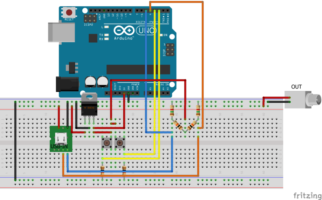
- Four 10k resistors, two of 470Ω, and two of 1.5k, which will support the library, since it will help it to achieve the necessary voltages for the QC3 protocol.
And the circuit diagram would be the following:

In this circuit, the power to the Arduino will run from the USB, which will start with 5v. By being able to increase up to 20v depending on the voltage we select, we will need a regulator that supports that maximum voltage, and powers our Arduino with stable 5v. These 5 volts will also power the voltage dividers used to achieve the voltage required by the QC protocol, as well as to power the buttons.
The code that we will use in our Arduino will be the following:
#include <QC3Control.h>

//Pin 4 for Data+
//Pin 5 for Data-

//See How to connect in the documentation for more details.
QC3Control quickCharge(4, 5);

#define waitTime 500

unsigned long latestPush = 0;

void setup() {
  attachInterrupt(digitalPinToInterrupt(2), decreaseV, RISING);
  attachInterrupt(digitalPinToInterrupt(3), increaseV, RISING);

  quickCharge.begin();
}

void loop() {
  //delay(5000);
  //quickCharge.incrementVoltage();
}

void decreaseV(){
  if (millis() > (latestPush + waitTime)){
    quickCharge.decrementVoltage();
    latestPush = millis();
  }
}

void increaseV(){
  if (millis() > (latestPush + waitTime)){
    quickCharge.incrementVoltage();
    latestPush = millis();
  }
}
As you can see, the code above is quite simple. We just wait for the buttons to interrupt and then we execute the corresponding function.
Currently the library does not have Feedback, so the voltage it has and thinks it has may not match. Over time I will try to create one that has Feedback.
I hope you liked it! Greetings!

