Today I bring you several circuits, which will help you protect your projects against reverse polarity. This will help you avoid damage to your circuit if at any time someone connects the power supply backwards.
First I’ll start with the most basic diode-based ones, then move on to the relay-based ones, and lastly I’ll use mosfets.
In my explanations, I will use the classical method of current circulation, which is from the positive pole of the source to the negative. In the real sense of the current, on the contrary, the circulation of the current would be from the negative pole to the positive pole.
Reverse polarity protection using a diode
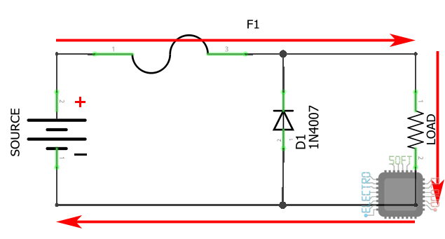
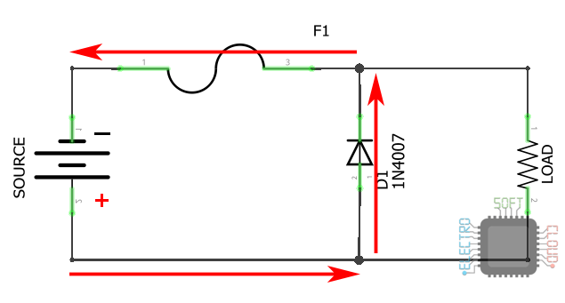
This type of protection is the simplest and most basic of all, but I only recommend it for low voltage and current circuits. A direct bias diode will be placed in this circuit, which will make it only conducts when the polarity is connected correctly.
The use of Schottky diodes is recommended, since the voltage drop in these is less. This will also cause less heat to be generated in them.
If we connect the power supply correctly, the current will circulate and our circuit will work normally.
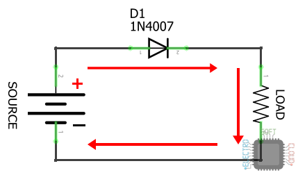
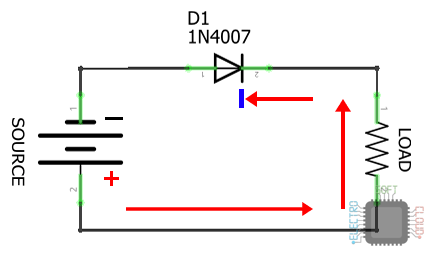
If, on the other hand, we connect the power supply incorrectly, the diode will block the passage of current and therefore protect our circuit.
- Advantages:
- Simple and cheap circuit
- Components are not damaged if the source is reversed
- Disadvantages:
- The voltage drop across the diode is dissipated as heat. This means that the more current, the greater the dissipation
Protection using a rectifier bridge
In this second reverse polarity protection circuit, we will use a rectifier bridge. The difference with the previous one is that with this bridge we will rectify the current, so that our circuit will work regardless of how it is connected.
Like the previous one, it is only recommended for low voltage and current circuits, since the heat dissipation of the diodes is proportional to the amount of current passing through them.
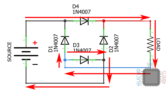
When connected as shown in the image above, diode D1 blocks current because it is reverse biased. Therefore, the current follows the path of D4 to our load. Once it leaves the load, it finally goes through diode D3 until it reaches the negative pole of the source.
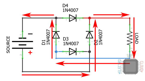
As you can see, even though the source is reversed the current also finds a correct path to our charge. This time, it will leave the positive pole and go through D2, which would be directly polarized. After going through the diode it would reach the load, and then it would go out to go through diode D1 and reach the negative pole of our source.
- Advantages:
- Simple circuit
- Our circuit would work independently of how the source is connected
- Components are not damaged if the source is reversed
- Disadvantages:
- The voltage drop across the diodes is dissipated as heat. This means that the more current, the greater the dissipation
Protection using a diode and fuse
This type of reverse polarity protection is based on connecting a fuse between our circuit and the load, and then protecting it with a diode in parallel with the source.
By connecting the source with the correct polarity our circuit will work normally.
However, when connected to reverse bias, the diode will go into direct bias, driving all current through it.
When this happens, the current through the fuse will be higher than the maximum withstand, and will melt opening the circuit and protecting it.
This type of circuit is widely used for its simplicity, but personally I do not think it is the best, since the diode tends to burn along with the fuse. This will cause that in addition to changing the fuse, it is necessary to change the diode. Also, during the brief instant that the fuse takes to blow, your circuit will be reverse biased, so if it is very sensitive, it may suffer the consequences.
That is why, in this circuit it is recommended to use a diode and a high speed fuse, in order to minimize the time during which the circuit is reverse biased.
- Advantages:
- The circuit is simple and can be used on a wide variety of circuits
- Disadvantages:
- The diode tends to burn out with the fuse, so it will be necessary to replace both
- During the instant it takes for the fuse to blow, your circuit is reverse biased.
Reverse polarity protection by diode, SCR and fuse
In this method you can see that it is a derivative of the previous one, only that we have added an SRC to it. This component will be the one that short-circuits if we connect the source incorrectly, blowing the fuse.
The advantage of this circuit is that the SCR can withstand more current than the diode, so it will hold until the fuse blows.
Like all the others, connecting the circuit with the correct polarity will work without problems.

However, when connected with reverse polarity this circuit will go through two phases.


As we can see, in the first phase the diode will lead to being in direct polarity. This diode will have a limiting resistance to prevent a lot of current from flowing, which will prevent it from burning out. Also in this phase the voltage of the thyristor gate will increase, causing it to trip.
In the second phase the Thyristor will have tripped and therefore will go into conduction, which will cause a short circuit and cause the fuse to blow.
- Advantages:
- The circuit is simple and can be used on a wide variety of circuits
- The Thyristor absorbs the current necessary to burn the fuse, so the diode does not burn
- Disadvantages:
- The time it takes to cut the current is longer by having to drive the diode and then the Thyristor. During that instant the circuit will be reverse biased
Reverse polarity protection using a diode and a relay
This circuit is a variation of the first, in which we put a diode in direct bias. The difference is that we will add a relay to avoid the voltage drop of the diode.
By avoiding this drop we will ensure that all the supplied voltage reaches our circuit. In addition, the diode will not dissipate as much heat having to deal only with the relay load.


When we connect the source correctly, the diode circulates the current as it is directly polarized. This activates the relay, which closes the contacts and allows current to flow to our load.
If, on the contrary, we connect the power supply incorrectly, the diode will be reverse biased and will not let current pass.

The diode that is in parallel with the relay does not affect operation. It is to protect the circuit from the voltage peaks generated by the relay coil.
- Advantages:
- No voltage drop between source and load
- Supported current is only limited by the relay used, so it supports much higher currents
- The diode only has to support the relay load, so it will not dissipate as much heat
- The idle circuit is open, so there is no conduction at any time when reversed.
- Components are not damaged if the source is reversed
- Disadvantages:
- The relay is mechanical, so it suffers from wear
- For high currents use a high quality relay or the contacts will burn
Reverse polarity protection with Mosfet
And we end with one of the circuits that I like the most. This circuit combines the need for the Mosfet to be polarized to conduct, together with its low resistance while driving.
For this circuit we will use a P type Mosfet Transistor, although by slightly varying the circuit we can use an N type. We will connect our source to the Drain pin, the load to the Source pin and the Gate pin we will connect it to ground. To avoid damage to the Mosfet in the case of using a voltage higher than that tolerated, we will use a zener diode together with a limiting resistor.


As it can be observed, when connecting the source correctly, the internal diode of the Mosfet begins to lead because it is directly polarized. This causes the Emitter voltage to increase and therefore the Base-Emitter difference. When this voltage reaches the saturation point, the Mosfet begins to conduct with almost no voltage drop.
In the event that the source is connected in reverse, the Base-Emitter voltage will be equal to zero. This will cause the Mosfet to stay cut and therefore not conducts. Also the internal diode of this will be reverse biased, so it will not let the current pass either.

If our circuit is going to work with a lower voltage than the maximum supported between the base and the emitter of our Mosfet, the Zener diode will become optional. This component would only serve for higher voltages, thus preventing damage to the Mosfet.
In addition, we can also use the N-type transistor variant by slightly varying the circuit. This type of transistor has the advantage that it usually has a lower resistance, being able to withstand more current and having a lower voltage drop.

An important thing to keep in mind is the resistance of the Mosfet in saturation (RdsOn). The lower this resistance, the lower the voltage drop in our Mosfet. That is why it is important to look at the data sheet to find one with the least resistance.
To give an example, we are going to compare the very widespread IRF540, with a WSR200N. The IRF540 has a saturation resistance (RdsOn) of 44m, which at 20A will give us a voltage drop of almost one volt (0.88v). For its part, the WSR200N has a saturation resistance of only 3.5m, so the voltage drop with 20A will be 0.07v.
In addition to the voltage drop, there would also be dissipation. The IRF540 would dissipate a power of 17.6W, requiring a heatsink, compared to the 1.4W of the WSR200N.
- Advantages:
- The voltage drop between the source and the load is minimal
- Low heat dissipation
- They withstand a lot of current, having 300A Mosfets and more.
- The idle circuit is open, so there is no conduction at any time when reversed.
- Components are not damaged if the source is reversed
- Disadvantages:
- The more current, the more voltage drop there will be and the more heat dissipation
- It requires a minimum voltage to enter saturation. Below that voltage it behaves like a variable resistance, generating more voltage drop and heat.
And well, so far my entry on protections against reverse polarity. I hope you liked it, and as always, comments are welcome.