This time I bring you a guide about STM32F103 (Bootloader and programming). This microcontroller has the advantage of having more capacity on almost everything compared with an Arduino (ATMega328p), having more SRAM, program memory, ADC and DAC resolution… for a little more money. More info into the Datasheet.
Furthermore also we can take a look into the pinout.
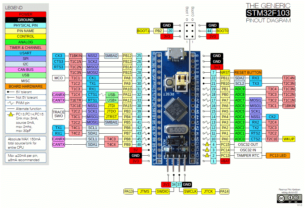
To have a better idea, Arduino Nano costs about 1.5€ while a STM32F103 costs about 2€. The STM32 have more CPU power, more memory, more I/O pins…
Leaving that apart, in this post I will focus on how to burn the bootloader and program it.
Boot Modes
Firstly, is important to know a bit about the boot modes, because we will use those modes later. Microcontroller have three basic modes:
| BOOT0 | BOOT1 | Mode |
| 0 | 0 | User flash (default mode) |
| 1 | 0 | System memory (bootloader) |
| 1 | 1 | SRAM memory |
Those boot modes are controled by the two jumpers on the board, which are marked as BOOT0 and BOOT1. Depending of which one we activate, the microcontroller will boot on one or another mode, allowing us to programm it.
User flash
Default boot mode and in which the microcontroller will boot when both BOOT jumpers are connected to 0. This mode will boot the program that was been programmed into the microcontroller. If doesn’t have any, then the booloader will be loaded.

System Memory
In this mode, the microcontroller will boot from the internal system memory, which contains the basic internal bootloader. This memory is Read Only, so you cannot burn another bootloader on it. However, this mode will allow you to program the microcontroller through UART. To enter on this mode you will have to change the BOOT0 jumper to 1 like the following image.

SRAM Memory
This mode will load a program from microcontroller SRAM, so you need to load that program into SRAM first. To enter in this mode, you have to set both jumpers to 1 like the following image.

STM32F103 Bootloader
Firstly, you have to know what the bootloader is. A bootloader is an small program executed when the microcontroller boots, and contains the basic functionalities. The STM32 internal bootloader for example, have the functionality of UART programming, but not USB programming. To solve this problem, there are another bootloaders that are stored on program memory (remember that bootloader is Read Only). Those bootloaders have the functionality of use the internal USB, converting it into a programmer, similar to UART programmer.
This is nothing strange, because the Arduino microcontroller (ATMega328p), also comes in a similar way. The only difference is that the Arduino boards comes with an USB to UART chip that adds this functionality. Conversely, if you are using that chip in standalone mode, you will need an external programmer.
On the STM32, far away to be a disadvantage is an advantage, because it allow you to use the USB as you need (for example a Gamepad), or like the bootloaders do, to program the microcontroller.
In this post I’ll talk to you about the two bootloaders I have used, which are working perfectly. Those bootloaders are STM32duino and STM32 HID, but personally, I preffer the HID because doesn’t need drivers.
- STM32duino: https://github.com/rogerclarkmelbourne/STM32duino-bootloader
- STM32 HID: https://github.com/Serasidis/STM32_HID_Bootloader
Download the bootloader
Now that we know what is a bootloader, we will proceed to download it. Above you can see two links to the source codes of those bootloaders, and also to download sections. A direct links to those sections will be binaries folder for SMT32duino, and releases if on the contrary, you prefer the SMT32 HID.
To know what file we must download, we will look at the pin where the builtin led is located.

If you take a look into the above image, you will see that the builtin led is on the PC013 pin, so you will have to download the bootloader with the pc13 in the filename.

Once is downloaded, we will proceed to burn it into the STM32 microcontroller.
Note: The Maple bootloader needs to install a driver to be recogniced by the computer, while the STM32 HID is detected without any extra driver.
Burn the bootloader
To burn the bootloader we need to install a program that will allow us to program the microcontroller, besides an USB->UART programmer. This program needs java to work, so first we need to download an install the latest Java version if is not already installed on your computer:
https://www.java.com/es/download/
Once Java is downloaded and installed, we can proceed to install the program to burn the bootloader. This program is called STM32Cube, and can be downloaded from the following link:
https://www.st.com/en/development-tools/stm32cubeprog.html#get-software
To download this program you will need an email address to receive a download link (required). Once downloaded and installed, we can proceed to burn the bootloader.
First we need to connect the STM32. We can do it following this picture, where you can see the connections.

Is very important to configure the BOOT jumpers like they are in the image: BOOT0 to 1 and BOOOT1 to 0, or the microcontroller will not be detected. Once is configured like the image, we will proceed to connect the UART programmer to the computer through USB, and we will open the program STM32CubeProgrammer (the installer will have created an icon on the desktop).
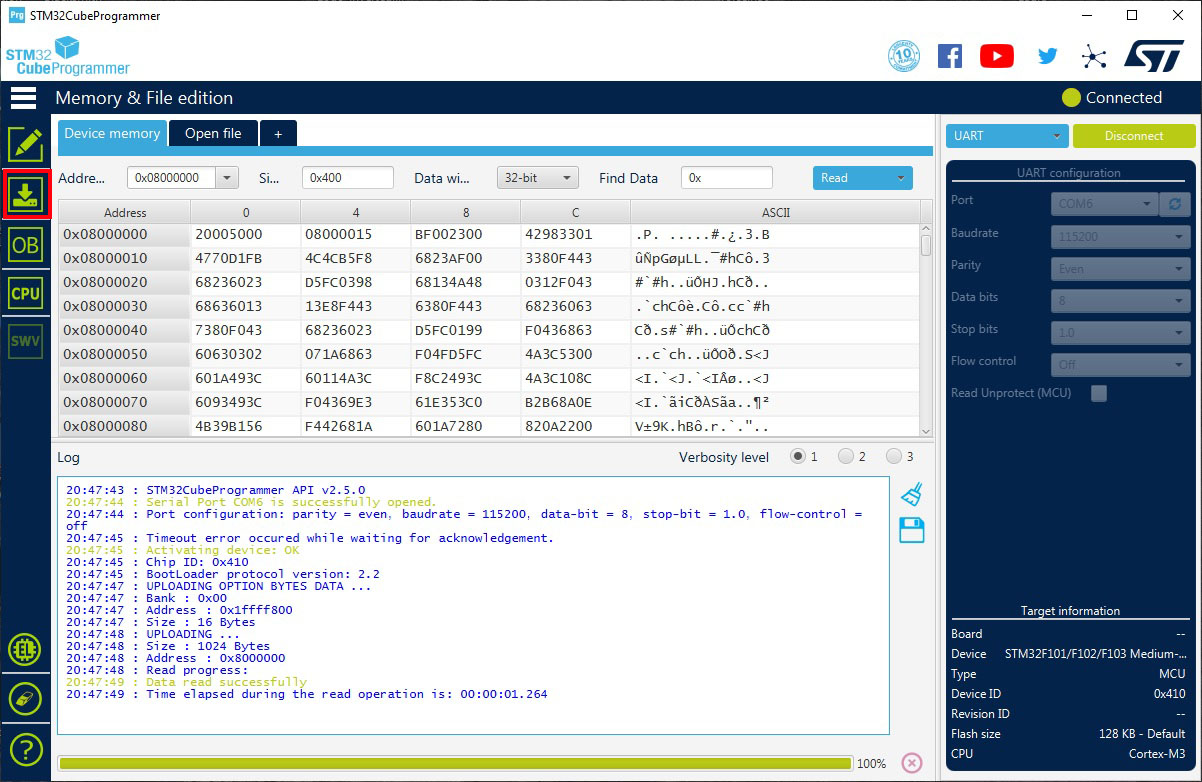
Once we have opened the program, we will see if the programmer is in the COM ports list, and if it is there, we will press Connect. Then the microcontroller will be detected and connected to the program, allowing us to upload a program (in this case the bootloader).
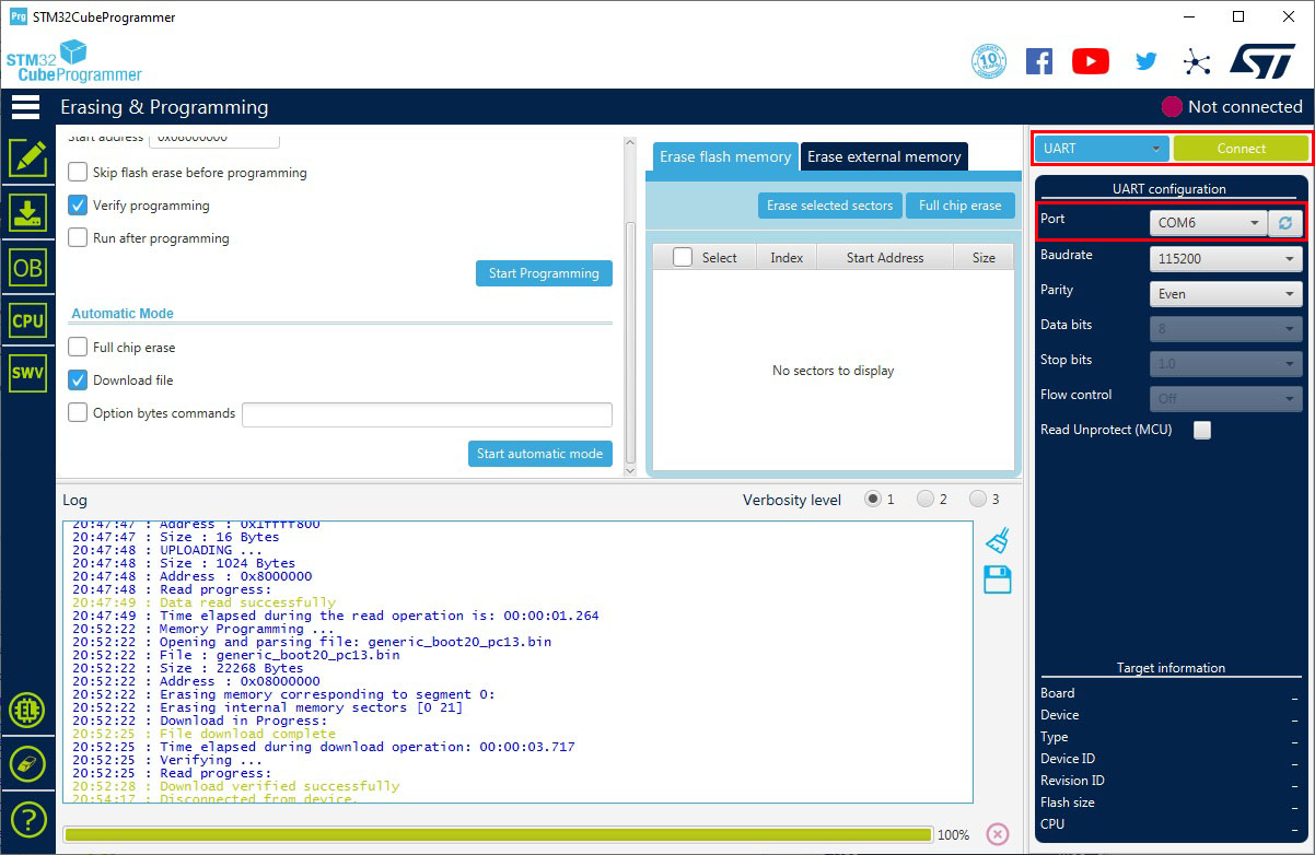
If you receive an error, check the connections, the Boot jumpers configuration, and the COM port. Once is connected, we have to press the download button on the left bar of the program.
On the new screen we will press the browse button to select the bootloader file that we want to burn.
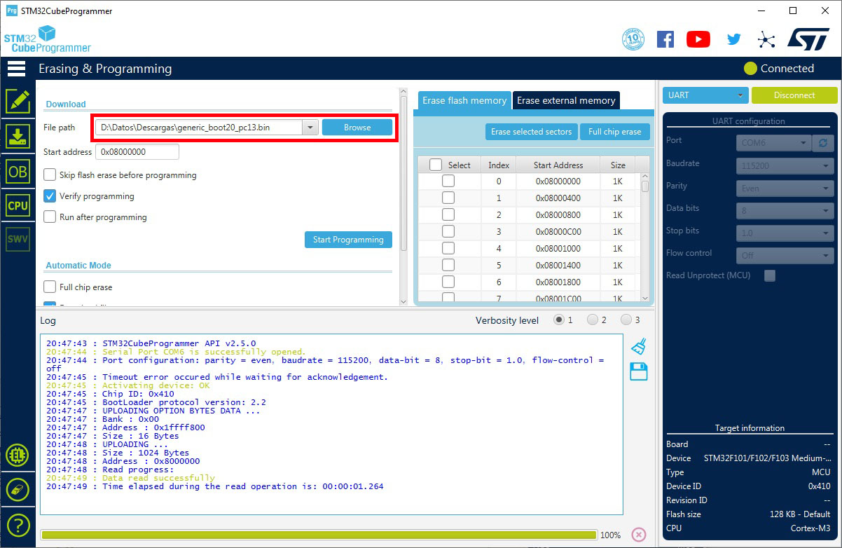
Once is selected, we will press Start Programming, to upload the file to the microcontroller.
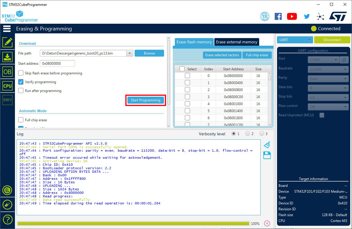
The progress bar in the bottom of the screen will show us that is programming the microcontroller, and once is the program is uploaded a confirmation message will be shown.
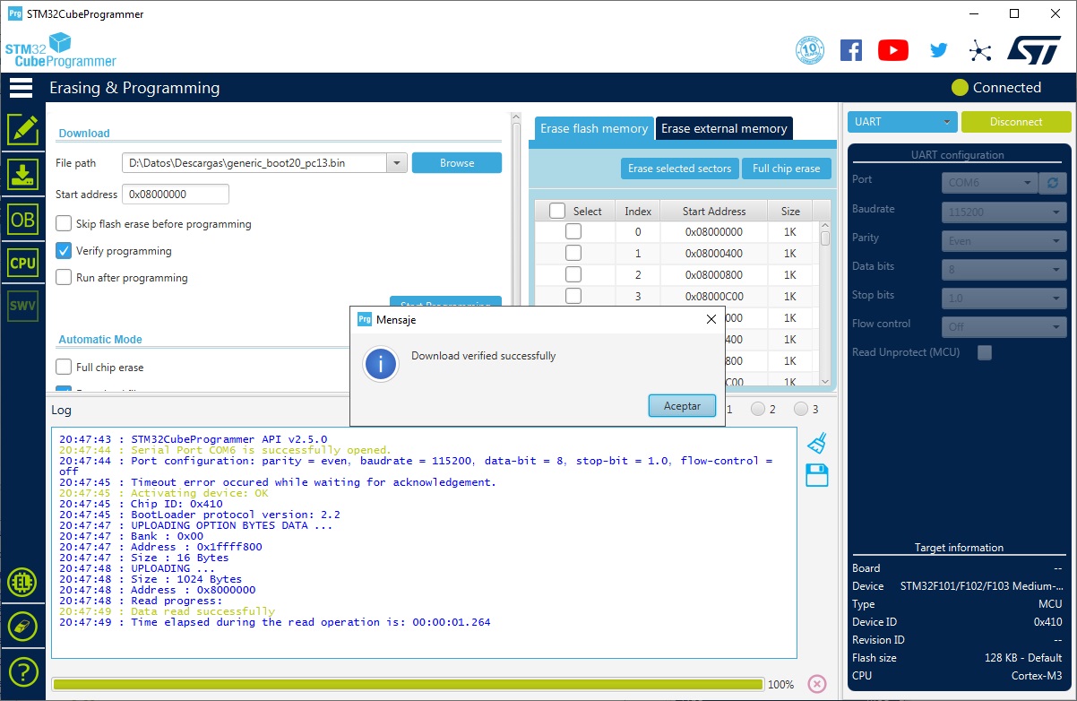
Finally, we will change the Boot jumpers to the default mode again (Both to 0), to boot the new installed bootloader, and now we will be able to program the microcontroller using the Arduino IDE.
Program the microcontroller
To program our STM32F103 with the bootloader already uploaded, the first thing we will have to do is download the configuration of the cards in the IDE. For this we go to File> Preferences.

In the new screen that will appear, click on the button to the right of the “Additional Card URL’s Management” section.

We add the following URL to the list.
https://github.com/stm32duino/BoardManagerFiles/raw/master/package_stmicroelectronics_index.json
And finally we close both windows giving OK in both. Now we will proceed to install the board, for which we will have to go to Tools> Board> Card Management

And in the new window that will open we look for STM32. In the result that will come out, we go down, since the install button is hidden by the long text, and we click on it to proceed to install it.

This process will take a while, so we wait and when it finishes we just close the window.
Once finished, we will have everything we need to program our microcontroller, we will proceed to connect it to the computer. To do this we make sure that both Boot jumpers are at 0 if we choose the Maple bootloader.
or on the contrary, we will set the BOOT1 jumper to 1 if we choose the HID bootloader.

Once the jumpers are configured, we proceed to connect the board to the PC directly (without the programmer used above to burn the bootloader), and then we will see how the PC detects it. In the case of Maple it will assign us a port, but in the case of HID it will not appear in the list of ports.
If we lean towards the Maple bootloader, it is very important to install the driver first or else the board will not be detected when it enters programming mode and therefore we will not be able to program it. To do this, we download the following ZIP file, unzip it, and execute the install_drivers.bat file that is inside the resulting folder.
Now that we have everything we need installed, we will proceed to open our Arduino sketch and program it. We select the options corresponding to the board we have and the bootloader that we have installed, and click on the program button.
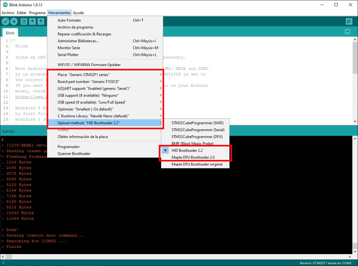
NOTE: Remember that in the case of using the STM32 HID bootloader the port option will not be selectable, but in the case of using the Maple bootloader, you will have to select the correct port.
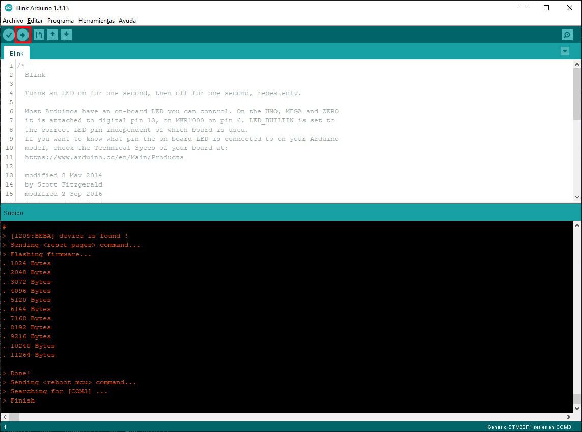
After a few moments of compilation, the program will be ready and uploaded to the microcontroller. In the case of having the HID bootloader, you will have to reset both jumpers to 0 for the STM32 to load the program. In the case of Mapple’s bootloader, both will remain at 0 and therefore you will not have to make any changes.
I hope you liked it and it helps you for your future projects. Greetings!
I’m glad it helped you. Thanks for your comment.
Is easy to just copy/paste, but if you don’t understand how it works then you will not be able to create anything interesting by yourself. That is why first I try to understand what I’m doing reading several places and researching into why they have done some things, and then I redact my guide trying to explain more less what I have learned. Also I’m a bit clueless and sometimes I use my own posts to remember things 😉
Best regards
Excellent tutorial explanation Daniel! I’ve followed too many attempts (both YouTube and textual) that leave out many of the steps and/or WHY you are doing the ones they tell you to do. You do an excellent job of explaining WHY you must do certain steps.