
Hello, today I bring you a basic tutorial about the pull-up and pull-down resistors, and the INPUT_PULLUP input mode of the Arduino pins.
This type of resistance will help your Arduino not be affected by electrical noise and receive errors in your measurements such as false pulsations on a button.
What is HIGH, LOW or FLOAT in digital electronics?
What? But we weren’t going to talk about pull-up and pull-down resistors. Yes, but I found it interesting that you knew the ways in which our Arduino pins can be.
In digital electronics, 0 and 1 are used to transmit data, and since you cannot send a number 0 or 1 through a cable, voltage values are used to indicate each of the states.
For the HIGH or 1 state a value of 5v will be used, and for LOW or 0 a value of 0v will be used. Of course nothing is perfect, and the signal is not going to be exactly at 0v or 5v (resistance and noise of the cables for example). To avoid interpretation errors, the circuits have a noise margin that allows them to interpret the signals as HIGH or LOW even though the voltage is not exactly 0v or 5v.
FLOAT, is when a pin is not in a fixed state and fluctuates (for example a loose cable connected to an Arduino pin). This can cause the state of our pin to vary between 0 and 1, and end up giving false positives.
What is a pull-up resistor?
A pull-up resistor is not any special resistance. It is a normal resistor connected in a concrete way to a pin of our microcontroller.
In the case of the pull-up resistor, the Arduino pin is connected to 5v or 3.3v through a resistor.

This causes that by default it has a HIGH value, and when we connect it to 0v by pressing the button, it will have a LOW state.
What is a pull-down resistor?
As with the pull-up resistor, a pull-down resistor is not a special resistor. In this case this resistance is connected to 0v, so by default it will have a LOW state.

When the button is pressed, our pin will change from a LOW state to a HIGH state.
What is it for?
Its main operation is to prevent the pin of our Arduino is in a FLOAT state, since it would fluctuate between HIGH and LOW. In this state we would receive false data and our program may not work properly.
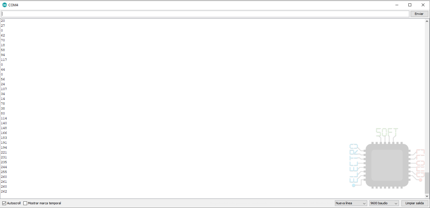
In the image you can see how the lack of resistance causes the values to fluctuate. Simply bringing your hand to the cable already generates a great change in the data, so it is very susceptible to external interference.
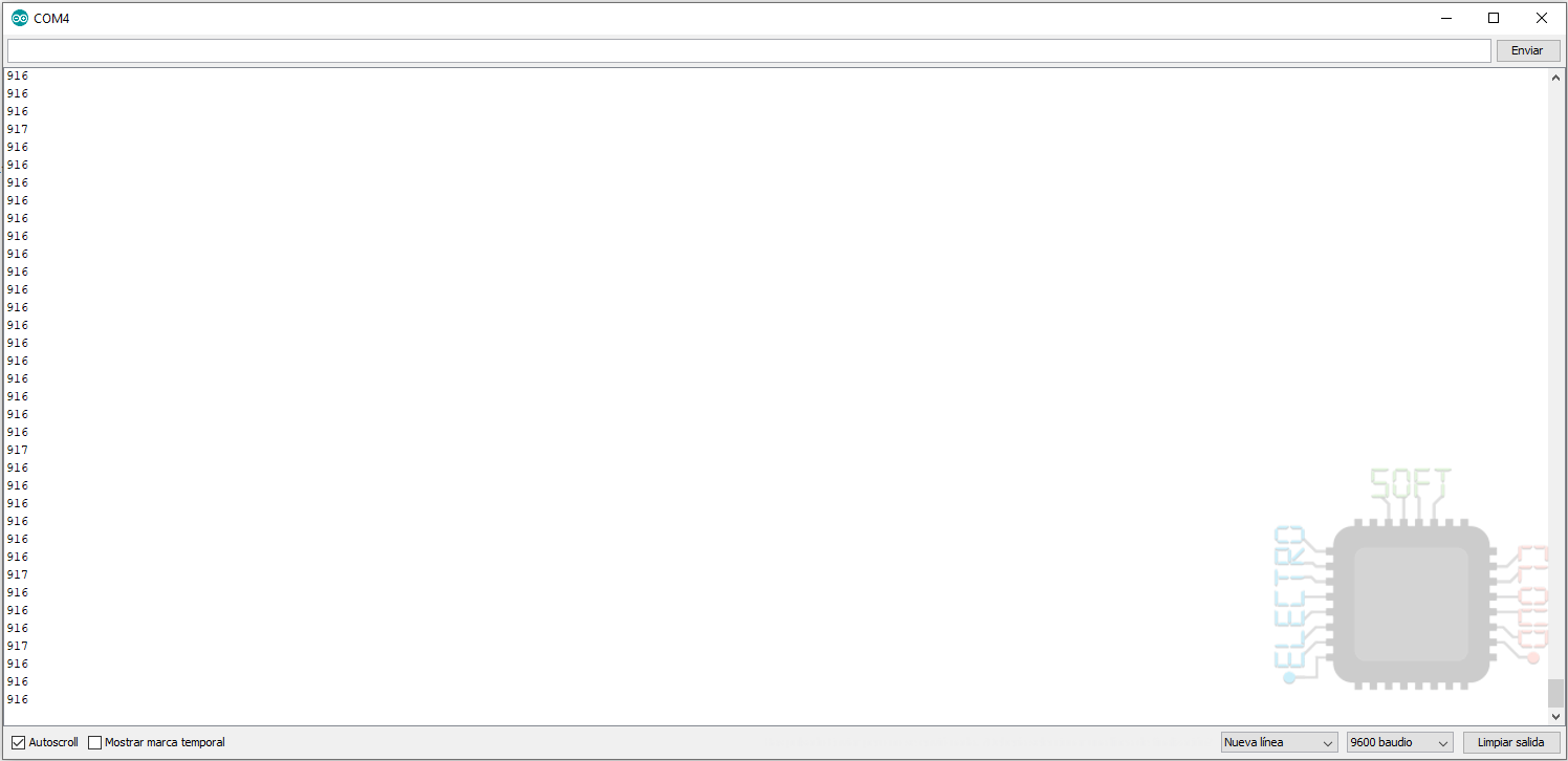
In the following images we can see how adding a pull-up or pull-down resistor solves the problem.
INPUT_PULLUP mode
I couldn’t finish the tutorial without talking about the INPUT_PULLUP mode available on the Arduino pins. What it does is connect an internal 20kΩ resistor of our Arduino, which is connected to 5v (HIGH). With this we will no longer need external pull-up resistance and we can save it in our circuit.
If you’re wondering if you could use INPUT_PULLDOWN, I also wondered and I’m afraid there is no such functionality. In case you want to use it, the only option you have is to use an external resistor.
To see how it works we will use the following sample code:
int analogPin = A3;
int val = 0;

void setup() {
  Serial.begin(9600);
  pinMode(analogPin, INPUT_PULLUP); // Activate the internal PULL resistor
}

void loop() {
  val = analogRead(analogPin);
  Serial.println(val);
  delay(100);
}
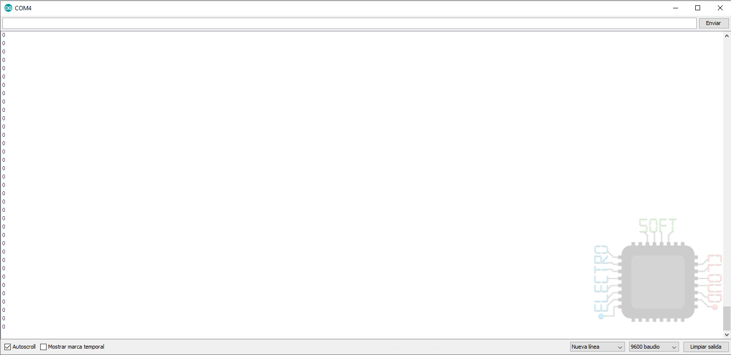
In it we simply activate the internal pull-up resistance and collect the data that the digital pin gives us. This means that even without connecting anything, the pin is always HIGH.
In the following image you can see the result it gives in a circuit that has nothing connected to the pin. This instead of being in FLOAT mode, it is in HIGH mode.

Notes
- Pin 13 cannot be used with INPUT_PULLUP, it is already connected to a resistor and a LED that are welded on the board. It can be used with an external pull-down resistor, but still the data would not be accurate, so I advise against its use
- The resistance used in both systems may be of the value you deem appropriate. In the example, a 10kΩ resistor is used, which generates a current of 0.5μa when the button is pressed.
Well up to here the guide of pull-up and pull-down resistors. As always, I hope it has served you well, and I am open to (constructive) comments and corrections.
Greetings!
pinMode(analogPin, INPUT_PULL); // Activate the internal PULL resistor
should be INPUT_PULLUP , you left out the UP
Thanks for the report, I’ll proceed to fix it.