Today I bring you how to use on Arduino the display from Nokia 5110 LCD and show graphics. If you missed any of the other two parts, I recommend you take a look.
Nokia 5110 LCD Display with Arduino (Part 1)
Nokia 5110 LCD and text with Arduino (Part 2)
On this occasion I am going to tackle the drawing part of this bookstore, with which we can draw circles, squares, images …
Index
Rectangle
One of the figures that allows us to create this library are the rectangles, being possible to create only the outline or the complete rectangle. For this we have two functions display.drawRect and display.fillRect.
The arguments that accept these functions are in order from left to right: X position, Y position, X size, Y size and color.

#include <SPI.h>
#include <Adafruit_GFX.h>
#include <Adafruit_PCD8544.h>

Adafruit_PCD8544 display = Adafruit_PCD8544(7, 6, 5, 4, 3);

void setup()   {
  display.begin();
  // init done
  display.clearDisplay();
  display.display();
  display.setContrast(50);

  // Draw a rectangle
  display.drawRect(0, 0, 60, 40, BLACK);
  display.display();
}

void loop() {
}

#include <SPI.h>
#include <Adafruit_GFX.h>
#include <Adafruit_PCD8544.h>

Adafruit_PCD8544 display = Adafruit_PCD8544(7, 6, 5, 4, 3);

void setup()   {
  display.begin();
  // init done
  display.clearDisplay();
  display.display();
  display.setContrast(50);

  // Draw a filled rectangle
  display.fillRect(0, 0, 60, 40, BLACK);
  display.display();
}

void loop() {
}
Rounded rectangle
Another form of rectangle that we have available is the rounded rectangle, and its is like the one of the rectangle, only that we will have to indicate how much we want to round the corners. Of course, just like the rectangle, we also have functions to create just the outline, or the solid rectangle with display.drawRoundRect and display.fillRoundRect
The arguments that accept these functions are in order from left to right: X position, Y position, X size, Y size, round size and color.

#include <SPI.h>
#include <Adafruit_GFX.h>
#include <Adafruit_PCD8544.h>

Adafruit_PCD8544 display = Adafruit_PCD8544(7, 6, 5, 4, 3);

void setup()   {
  display.begin();
  // init done
  display.clearDisplay();
  display.display();
  display.setContrast(50);

  // Draw a rounded rectangle
  display.drawRoundRect (0, 0, 60, 40, 8, BLACK);
  display.display();
}

void loop() {
}

#include <SPI.h>
#include <Adafruit_GFX.h>
#include <Adafruit_PCD8544.h>

Adafruit_PCD8544 display = Adafruit_PCD8544(7, 6, 5, 4, 3);

void setup()   {
  display.begin();
  // init done
  display.clearDisplay();
  display.display();
  display.setContrast(50);

  // Draw a filled rounded rectangle
  display.fillRoundRect (0, 0, 60, 40, 15, BLACK);
  display.display();
}

void loop() {
}
Circle
Of course, we could not miss the circles in the drawing section. For this we have two functions like the rest, which will allow us to draw the outline or a solid circle. These functions are display.drawCircle and display.fillCircle.
These functions accept four arguments, which are from left to right: X position of the center, Y position of the center, radius of the circle, and color. It is important to note that the position is the center of the circle.

#include <SPI.h>
#include <Adafruit_GFX.h>
#include <Adafruit_PCD8544.h>

Adafruit_PCD8544 display = Adafruit_PCD8544(7, 6, 5, 4, 3);

void setup()   {
  display.begin();
  // init done
  display.clearDisplay();
  display.display();
  display.setContrast(50);

  // Draw a rounded rectangle
  display.drawCircle(42, 24, 20, BLACK);
  display.display();
}

void loop() {
}

#include <SPI.h>
#include <Adafruit_GFX.h>
#include <Adafruit_PCD8544.h>

Adafruit_PCD8544 display = Adafruit_PCD8544(7, 6, 5, 4, 3);

void setup()   {
  display.begin();
  // init done
  display.clearDisplay();
  display.display();
  display.setContrast(50);

  // Draw a rounded rectangle
  display.fillCircle(42, 24, 20, BLACK);
  display.display();
}

void loop() {
}
Triangle
Luckily, triangles have also been accepted into the group of polygons that we can draw, so as with the rest, we can draw them with this library. For this we have the display.drawTriangle and display.fillTriangle functions available, which as with all the polygons seen so far, are used to create the solid outline or triangle.
Estas funciones aceptan como argumentos las coordenadas de las tres esquinas, siendo estos x0, y0, x1, y1, x2, y2, además del color del triángulo.

#include <SPI.h>
#include <Adafruit_GFX.h>
#include <Adafruit_PCD8544.h>

Adafruit_PCD8544 display = Adafruit_PCD8544(7, 6, 5, 4, 3);

void setup()   {
  display.begin();
  // init done
  display.clearDisplay();
  display.display();
  display.setContrast(50);

  // Draw a rounded rectangle
  display.drawTriangle(20, 0, 0, 40, 40, 40, BLACK);
  display.display();
}

void loop() {
}

#include <SPI.h>
#include <Adafruit_GFX.h>
#include <Adafruit_PCD8544.h>

Adafruit_PCD8544 display = Adafruit_PCD8544(7, 6, 5, 4, 3);

void setup()   {
  display.begin();
  // init done
  display.clearDisplay();
  display.display();
  display.setContrast(50);

  // Draw a rounded rectangle
  display.fillTriangle(20, 0, 0, 40, 40, 40, BLACK);
  display.display();
}

void loop() {
}
Line
And we are already nearing the end of this guide on how to use the display of the Nokia 5110 LCD and show graphics, but I couldn’t finish it without teaching you how to draw lines on our display.
The lines are from the simplest drawings there are, so we only need to indicate the start and end coordinates, as well as the color of the line. The function that will allow us to create lines is display.drawLine, and this function accepts 5 arguments: x0, x1, y0, y1.

#include <SPI.h>
#include <Adafruit_GFX.h>
#include <Adafruit_PCD8544.h>

Adafruit_PCD8544 display = Adafruit_PCD8544(7, 6, 5, 4, 3);

void setup()   {
  display.begin();
  // init done
  display.clearDisplay();
  display.display();
  display.setContrast(50);

  // Draw a rounded rectangle
  display.drawLine(10, 10, 74, 38, BLACK);
  display.display();
}

void loop() {
}
Pixel
One of the good things about this library is that it allows us to control the pixels independently. For this we will use the function display.drawPixel, to which we will indicate the coordinate and the color that we want the pixel to have.
#include <SPI.h>
#include <Adafruit_GFX.h>
#include <Adafruit_PCD8544.h>

Adafruit_PCD8544 display = Adafruit_PCD8544(7, 6, 5, 4, 3);

void setup()   {
  display.begin();
  // init done
  display.clearDisplay();
  display.display();
  display.setContrast(50);

  // Draw a rounded rectangle
  display.drawPixel(10, 10, BLACK);
  display.display();
}

void loop() {
}
Bitmap
Lastly, to finish the guide for using the display Nokia 5110 LCD and show graphics, but no less important (in fact it is quite important), we will see how to show images. The Adafruit library provides us with a function that will allow us to show bitmaps on our display. Of course, our display is limited to black and white, so we will have to get an image with those characteristics.
To do this, the first thing we have to do is make sure that our image fits on the display. Since the resolution is 84×48, we will have to resize the image to a size that is equal to or less, save it as bmp and finally convert it to a bit array. For this, we have several programs and options online, so here I will give you an online option, and another with a program.
Online
To convert the image online, we can use the following tool:
http://javl.github.io/image2cpp/
In it we simply follow the next steps and it will be ready.
We give the button choose files and select the image to convert

In image settings we put the display size, which as we remember is 84×48, and also select the option scale to fit – keeping proportions in the dropdown. If we want to center it horizontally we will also select that option. In addition, just below we will see the preview of how it will look.


Finally, in output we select the Arduino Code option, we put a variable identifier and we give Generate Code

With this we will have the variable that we need to pass to the function so that it displays our image.
Program
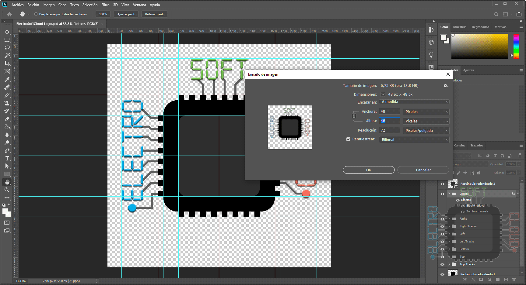
Converting the image with a program is a more tedious process, since we will first have to resize the image ourselves. For this we can use our favorite editing program, which in my case is Photoshop.
First we resize the image to a size that fits on the display.
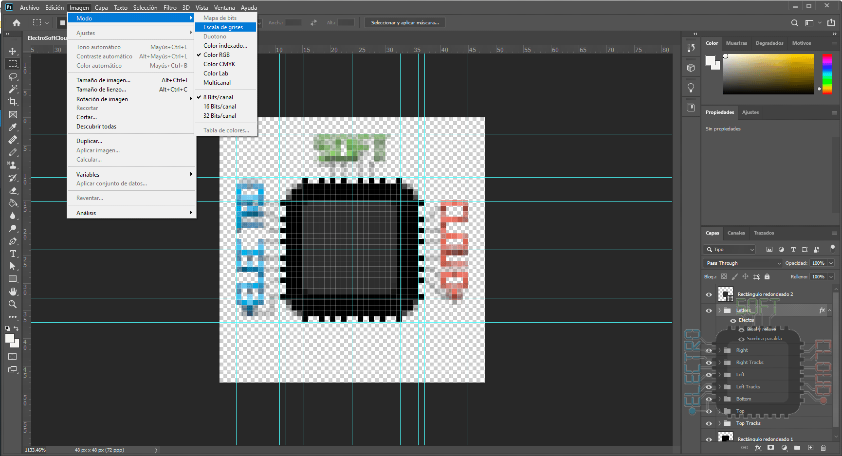
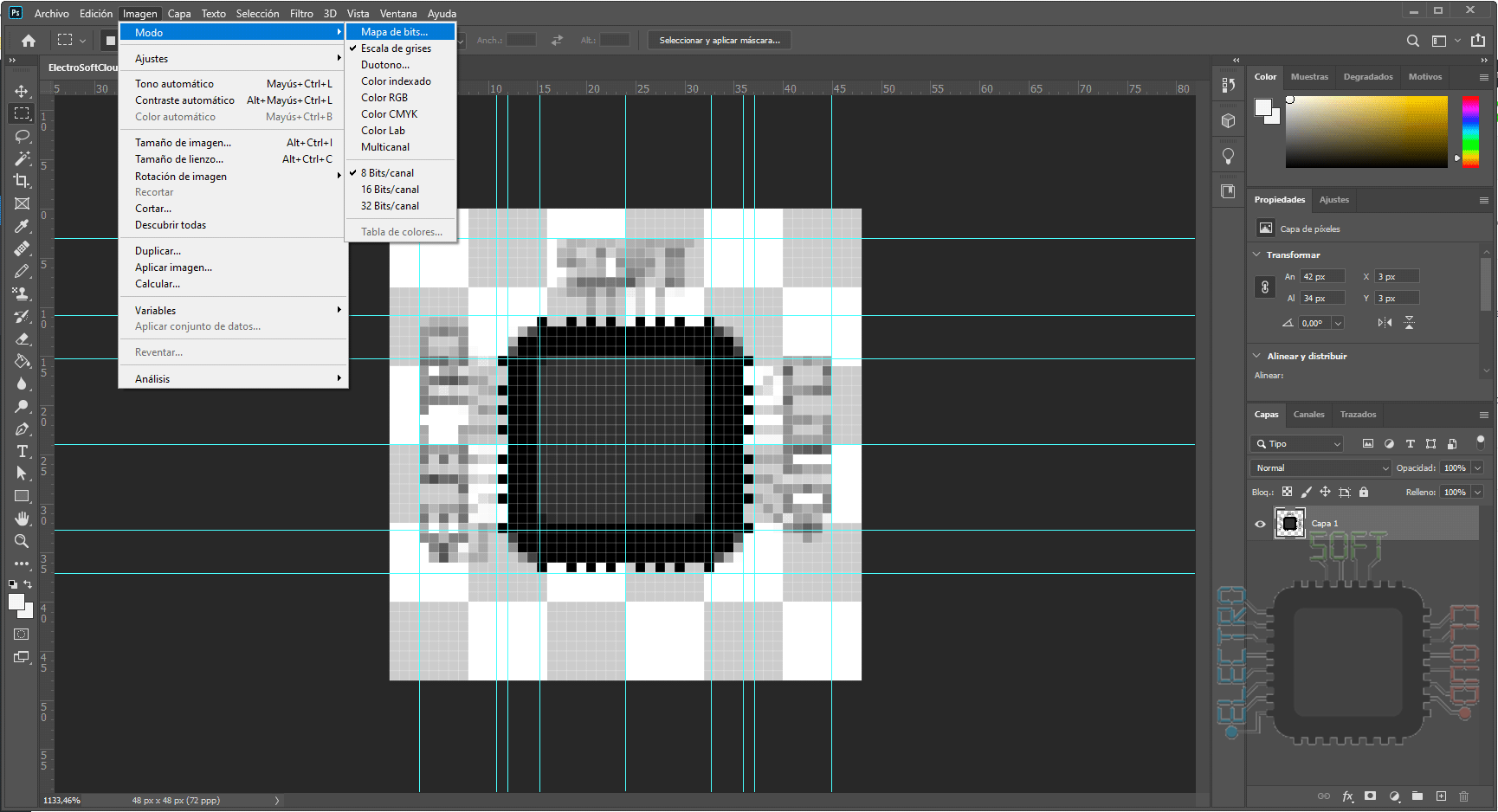
Once resized, we will proceed to convert it to a bit image, going through grayscale to eliminate the color and then selecting the Bitmaps option.
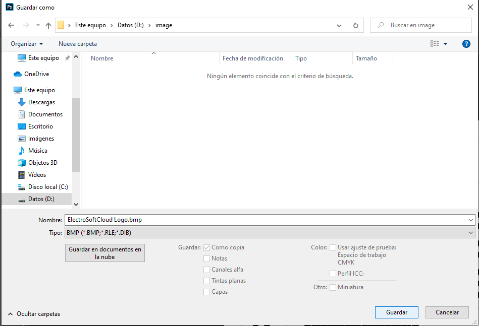
Once done, we will save it as a BMP format to be compatible with the conversion program.
Of course, depending on the image, it may look better or worse. In my case the image has many details and it ends up looking a little bad, but it serves as an example.
Once we have our image in BMP format, we will proceed to convert it to an array of bits, which will be the one that the function will use to draw it. You can download this program from the following link:
Once we have it, we open it and load our image from the File -> Load Image menu
Once loaded, we configure the options as the following image:

We will notice that below where it puts Table Name we will have to indicate the name of the resulting array, and the size must be the image size. Then we will give it to save from File -> Save output.

This will give us a text file, in which we will have the array that we will use in our program to display the image.

NOTE: The program does not add PROGMEM to the variable, which will cause that variable to be saved in the programming memory instead of in the SRAM. Therefore I recommend adding it just before the equal so as not to fill the SRAM of our Arduino.
Draw the image
Once we have the image as an array regardless of the method we have used, we can proceed to display it on the display with the function display.drawBitmap.
This function requires 6 arguments, which are: x position, y position, variable of our image, size x of the image, size y of the image, and color to be used. It is important that we indicate the size of the image correctly, or else it will not look good.
#include <SPI.h>
#include <Adafruit_GFX.h>
#include <Adafruit_PCD8544.h>

Adafruit_PCD8544 display = Adafruit_PCD8544(7, 6, 5, 4, 3);

const unsigned char ElectroSoftCloudLogo [] PROGMEM = {
0x00, 0x00, 0x00, 0x00, 0x00, 0x00, 0x00, 0x00, 0x00, 0x00, 0x00, 0x00, 0x00, 0x00, 0x00, 0x00,
0x00, 0x00, 0x00, 0x00, 0x12, 0x24, 0x00, 0x00, 0x00, 0x00, 0x4B, 0x08, 0x00, 0x00, 0x00, 0x00,
0x28, 0xE4, 0x00, 0x00, 0x00, 0x00, 0x14, 0x88, 0x00, 0x00, 0x00, 0x00, 0x57, 0xCC, 0x00, 0x00,
0x00, 0x00, 0x10, 0x00, 0x00, 0x00, 0x00, 0x00, 0x08, 0x00, 0x00, 0x00, 0x00, 0x00, 0x02, 0x40,
0x00, 0x00, 0x00, 0x01, 0x2A, 0x54, 0x80, 0x00, 0x1D, 0x07, 0xFF, 0xFF, 0xC0, 0x00, 0x01, 0x0F,
0xFF, 0xFF, 0xF0, 0x00, 0x08, 0x0F, 0xFF, 0xFF, 0xF0, 0x00, 0x1F, 0x1F, 0xFF, 0xFF, 0xF8, 0xB0,
0x01, 0x0F, 0xFF, 0xFF, 0xF0, 0x88, 0x1E, 0x8F, 0xFF, 0xFF, 0xF0, 0x00, 0x02, 0x1E, 0xF7, 0xBF,
0xFC, 0x98, 0x15, 0x0F, 0x7F, 0xDB, 0xF0, 0x80, 0x10, 0x5F, 0xF7, 0xFF, 0xF9, 0x00, 0x00, 0x0F,
0xFF, 0xFF, 0xF0, 0xA8, 0x11, 0x1F, 0xFF, 0xFD, 0xFA, 0x80, 0x00, 0x8F, 0x77, 0xBF, 0xF0, 0xA8,
0x15, 0x0F, 0xFF, 0xFF, 0xF0, 0xF0, 0x05, 0x5F, 0xFF, 0xFF, 0xF8, 0x00, 0x10, 0x0F, 0xBD, 0xDB,
0xF0, 0xC8, 0x1F, 0x1F, 0xFF, 0xFF, 0xFA, 0x20, 0x01, 0x0F, 0xEF, 0xFF, 0xF0, 0xB8, 0x00, 0x3F,
0xFF, 0xFB, 0xF8, 0x80, 0x05, 0x8F, 0xBE, 0xFF, 0xF2, 0x48, 0x14, 0x0F, 0xFF, 0xBF, 0xF1, 0x60,
0x01, 0x1F, 0xFF, 0xFF, 0xF8, 0x30, 0x1A, 0x0F, 0xFF, 0xFF, 0xF0, 0x20, 0x06, 0x47, 0xFF, 0xFF,
0xF0, 0x00, 0x05, 0x03, 0xFF, 0xFF, 0xC0, 0x00, 0x00, 0x01, 0x2A, 0x54, 0x80, 0x00, 0x00, 0x00,
0x00, 0x00, 0x00, 0x00, 0x00, 0x00, 0x00, 0x00, 0x00, 0x00, 0x00, 0x00, 0x00, 0x00, 0x00, 0x00,
0x00, 0x00, 0x00, 0x00, 0x00, 0x00, 0x00, 0x00, 0x00, 0x00, 0x00, 0x00, 0x00, 0x00, 0x00, 0x00,
0x00, 0x00, 0x00, 0x00, 0x00, 0x00, 0x00, 0x00, 0x00, 0x00, 0x00, 0x00, 0x00, 0x00, 0x00, 0x00,
0x00, 0x00, 0x00, 0x00, 0x00, 0x00, 0x00, 0x00, 0x00, 0x00, 0x00, 0x00, 0x00, 0x00, 0x00, 0x00
};

void setup()   {
  display.begin();
  // init done
  display.clearDisplay();
  display.display();
  display.setContrast(50);

  // Draw a rounded rectangle
  display.drawBitmap(0, 0,  ElectroSoftCloudLogo, 48, 48, BLACK);
  display.display();
}

void loop() {
}
I hope you liked this guide about how to use on Arduino the display Nokia 5110 LCD and show graphics, and as always, comments are welcome;)
Greetings!!