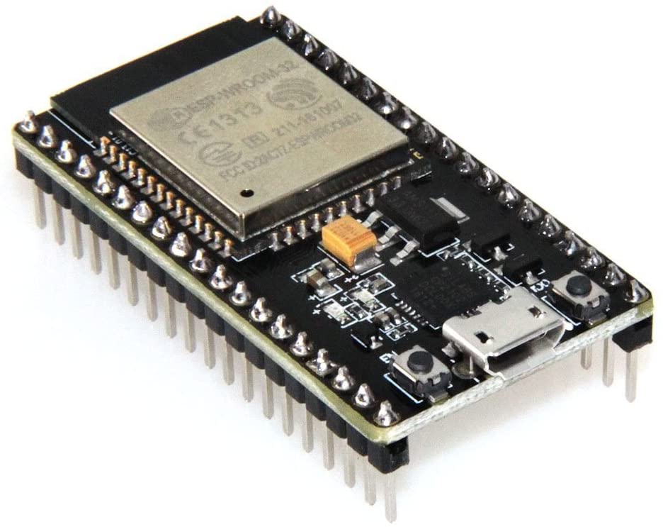
This time I am going to talk about how to start using our ESP32 microcontroller. In all traits this microcontroller is superior to most Arduinos, but it also consumes more power. This must be taken into account because depending on our project, it may be to kill flies with cannon shots.
Other than that, I understand that you have come here to learn how to get started with this microcontroller, so in this post I will teach you how to install the board in our Arduino IDE, and burn our first Sketch. If you have already added external cards before like STM32 or ESP8266, I will tell you that the process is the same, so it is not complicated.
información básica
Before starting to use our microcontroller, we will have to familiarize ourselves with it to learn how to use it better. Therefore, we will start by looking first at the pinout of the ESP32 board.
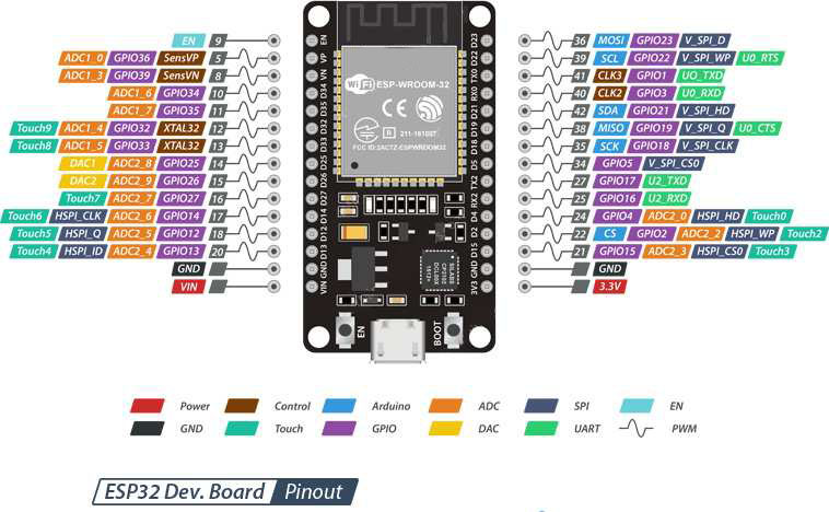
As you can see, we have a lot of ports for our sensors and others. It is also important that we have the datasheet of this microcontroller, because in it we see very interesting and important data. This datasheet can be downloaded from the espressif page, but I will leave you a PDF of the model that I have in case it works for you or the links on its website will no longer be available:
https://www.espressif.com/en/support/documents/technical-documents
Once we are familiar with our microcontroller, we can start with the fun part: configuring it and starting to upload sketches to it.
Add ESP32 board repository in Arduino IDE
The first thing we have to do is install the card in our Arduino IDE. The problem is that this card does not exist in the official repositories, so we will have to install an external one. To do this, we will follow these steps:
We will open the Arduino IDE and go to the menu File -> Preferences.
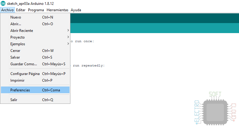
There we will see that in the Settings tab there is a text box at the bottom that says Additional Card URLs Manager. We will press the button on the right.
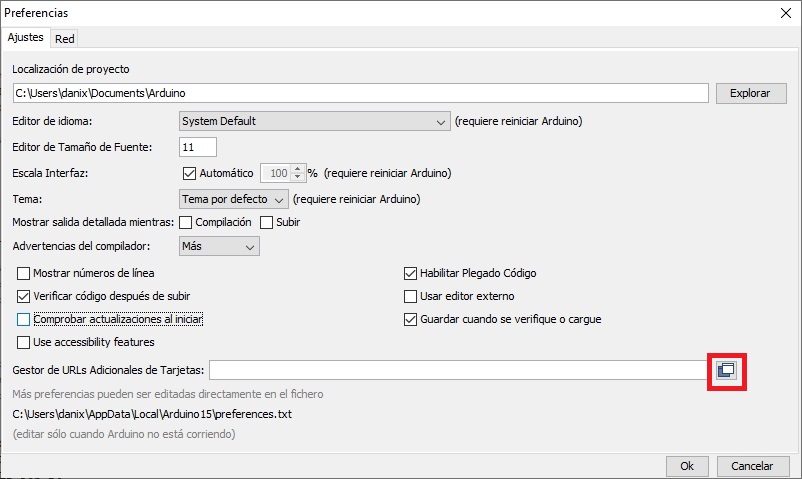
This will open another window with a list of cards, which will be empty if we don’t add any before.
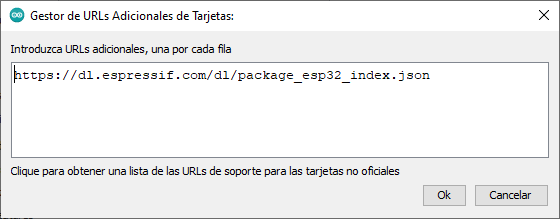
In this window we paste the following URL and give Ok
https://dl.espressif.com/dl/package_esp32_index.json
We accept the preferences window as well and we will already have the ESP32 board repository installed in our Arduino IDE.
Installing the cards
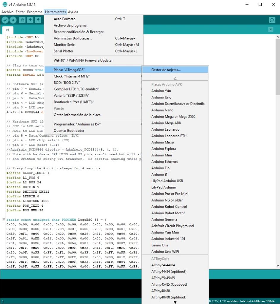
Now that we have the repository installed, we will only have to install the card in the program. To do this we will go to the menu Tools -> Board -> Board manager.
In the new window that will open we will look for ESP32 and we will install
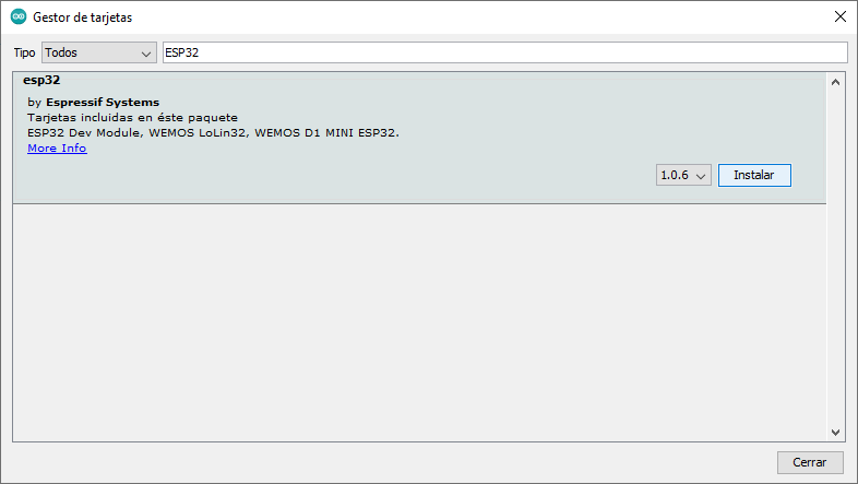
And with that we will have the card installed in our Arduino IDE.
Upload your first sketch
Now what we have left, once we have installed the cards in the IDE, is to upload our first skech. For this we will start with a simple one such as turning on and off the led of the plate. Of course this will depend on whether your plate has an LED or not …
To do this, we will connect the board to our PC and it will be detected automatically (at least in Windows 10). Now we will select the correct settings for our board, which by rule tend to be the default.
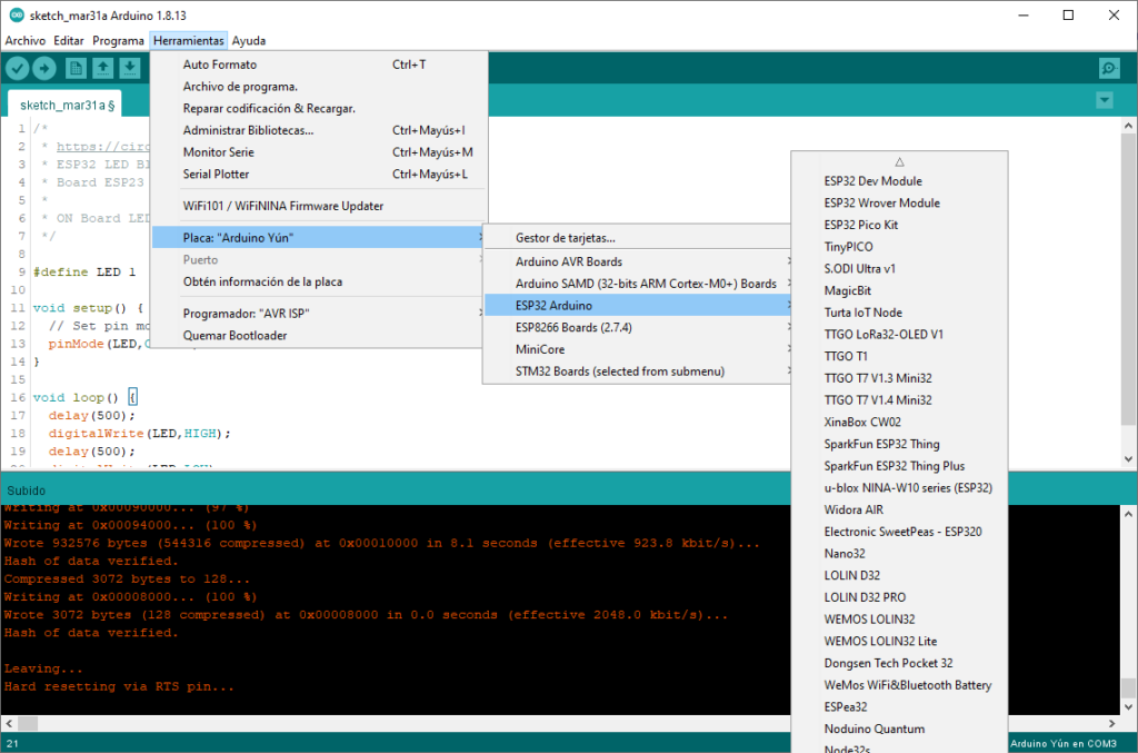
As you can see, there are a large number of cards in the list, so if your card is in it, it is best to select it. In my case I have a WROOM-32 card, which is not on the list, but the ESP32 Dev Module option served me perfectly. Once the card is selected, we will enter the Tools menu again and we will see that a lot of options have appeared, but since this is an introductory post I will not delve into them. Among those options, we have the option to select the port as if it were an Arduino, so we select the port where our board is.
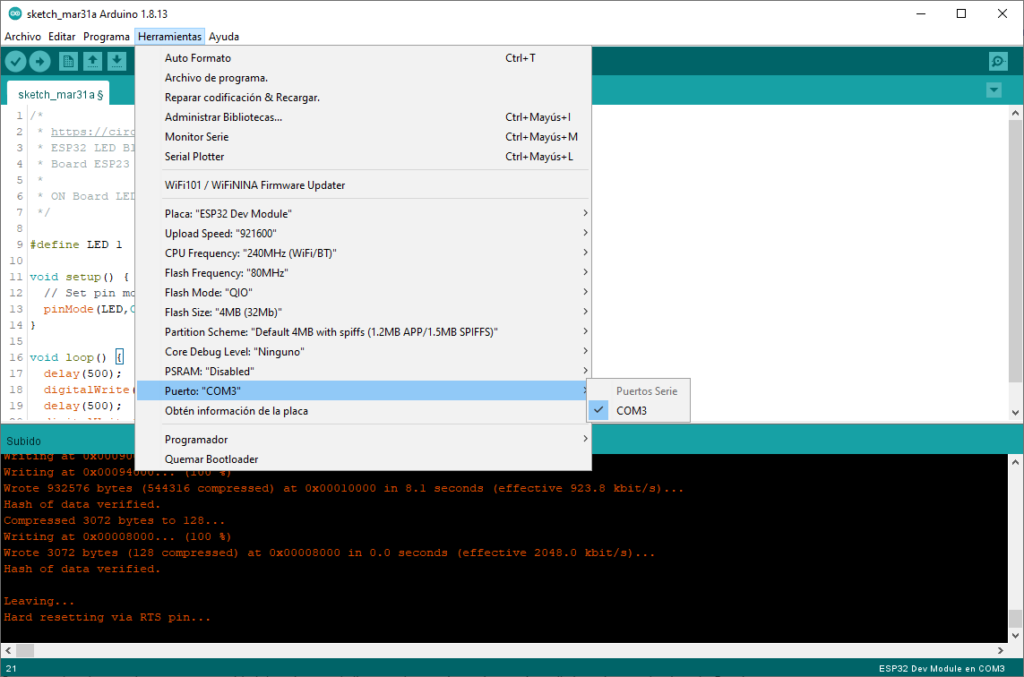
And with this we can upload our sketch to ESP32 without problems. Here you have an example of the Blink adjusted to the ESP32, which worked perfectly on my motherboard. If yours has the led on another pin, you will have to change the define at the beginning to indicate in which port it is installed:
/*
 * ESP32 LED Blink Example
 * Board ESP23 DEVKIT V1
 *
 * ON Board LED GPIO 2
 */

#define LED 1

void setup() {
  // Set pin mode
  pinMode(LED,OUTPUT);
}

void loop() {
  delay(500);
  digitalWrite(LED,HIGH);
  delay(500);
  digitalWrite(LED,LOW);
}
Once the Sketch is created, we will press the upload button as we would with Arduino and you will be able to see how the internal led of your card begins to blink.
Note
In some cases, extra steps may be necessary to upload your Sketch. For example, with NodeMCU it is necessary to select the board “DOIT ESP32 DEVKIT V1”, and keep the BOOT button pressed while uploading the Sketch (thanks Nicolas Kuran for the note).
Greetings and do not hesitate to comment if you liked it or think I should improve.

